


HARSFEN0602
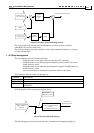
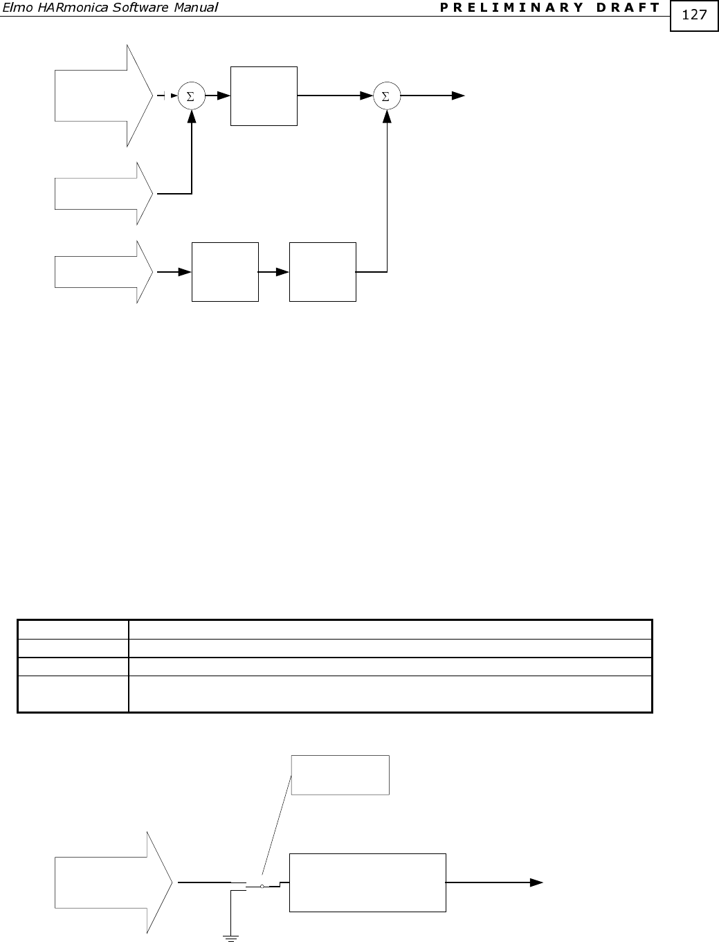
Auxiliary input
Analog input 1
(-10 to 10 Volts)
AG[2]
Count/sec/
Volt
Auxiliary speed command
AS[1]
`
-
Speed
estimator
FR[2]
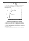
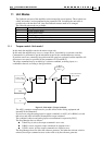
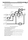
Figure 19: Auxiliary speed command generation
The analog input is most useful when the Harmonica serves as an inner controller,
embedded in an external control loop.
The auxiliary encoder speed input enables to issue speed commands relative to a conveyor
or other moving object.
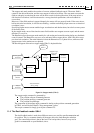
11.2.3 Stop management
The stop manager does the following functions:
- Bring the motor to stop upon software or hardware ST command.
- Bring the motor to stop when the speed demand is positive and FLS (Forward
Limit Switch) is active.
- Bring the motor to stop when the speed demand is negative and RLS (Reverse
Limit Switch) is active.
- Prevent acceleration or deceleration beyond the motor torque limits.
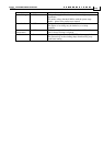
The parameters relevant to the stop manager are:
Command Description
SD Maximum motor acceleration/deceleration, counts/sec
2
LV[2],HV[2] Speed command limit
IL[] Input logic – define digital inputs as hard-stop, or as directional limit switches
(RLS,FLS).
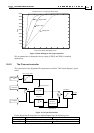
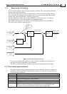
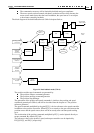
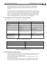
A block diagram of the stop manager is given below.
Reference generator
output (software +
auxiliary)
SD
Acceleration/Deceleration
Limiter
LV[2],HV[2] speed limiter
Command to
Speed Controller
-
Stop condition
(Stop, RLS, FLS)
0
Figure 20: Speed mode Stop Manager
The Stop-Manager prevents the speed-controller command from changing abruptly by