


HARSFEN0602
Command Description
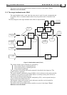
SF Smooth Factor: The time in milliseconds required to develop the full acceleration
of AC and deceleration of DC.
ST Stop command, activate profiler stop mode with Deceleration=SD
VH[2] Maximum speed command. Units counts/sec.
VL[2] Minimum speed command (bound on speed command from below, negative
value). Units counts/sec.
IL[] Map functions to digital inputs: Digital inputs may function as hardware ST or BG
instructions.
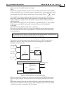
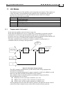
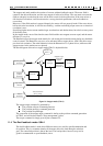
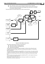
The algorithm of the acceleration-limited software speed command is listed below:
1. Any new BG command accepted by software or by hardware? If yes, update the
speed target to the value to JV, and also update the permitted acceleration and
deceleration to the values of AC and DC.
2. If the speed target and the speed command are positive, and the speed target is
greater than the speed command, select AC for the acceleration limit. If the speed
target and the speed command are negative, and the speed target is less than the
speed command, select also AC. Otherwise select DC for the acceleration limit.
3. Advance the speed command towards the speed target as much as the selected
acceleration/deceleration permits. In the trivial case where the speed command
already equals the speed target, do nothing.
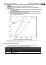
The acceleration limited software speed command is fed to a smoothing filter.
The smoothing filter limits the rate of developing the full acceleration or deceleration.
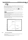
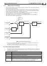
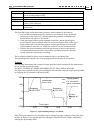
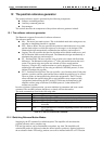
Example:
This example demonstrates the concepts of target speed and speed command. It also demonstrates
the AC and DC acceleration limits.
Let MO=1; JV=4000; AC=100000; DC=200000; SD=10
6
; PM=1; RM=0; SF=0; BG;
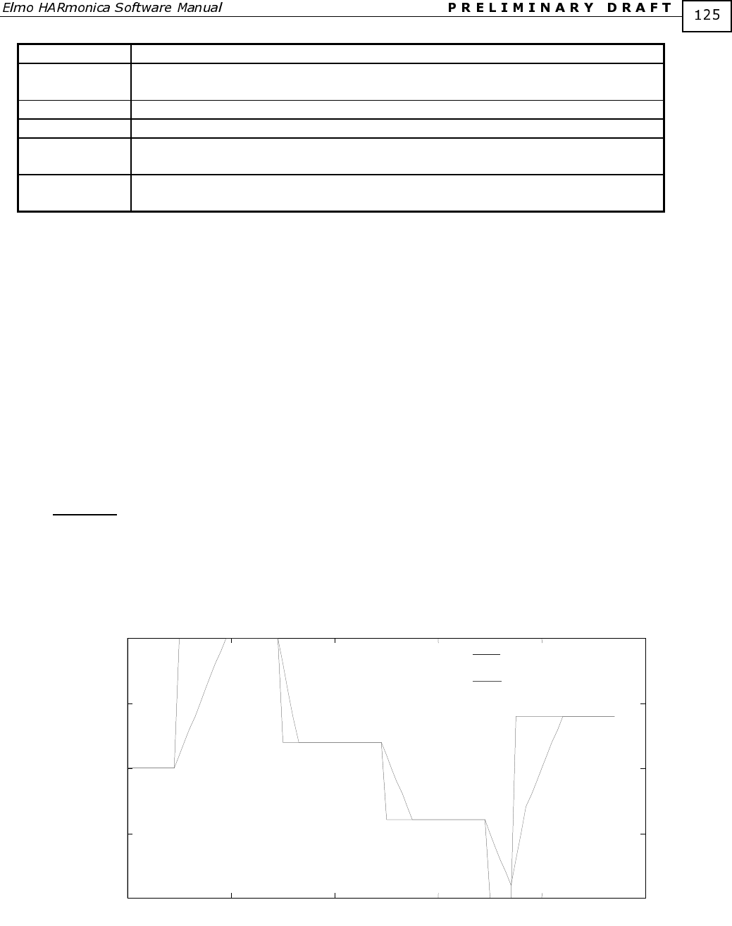
The figure below depicts how the speed command to the controller tracks the target speed specified
by changing the JV parameter, followed by a BG.
0
0.02
0.04
0.06
0.08
0.1
-1000
-500
0
500
1000
Target speed
Un-smoothed
speed command
Accelerat
e
to JV=1000
Decelerate
to JV=200
Accelerat
e
to JV=-
400
On the
fly
change of
JV
Time (sec)
Figure 17 – Speed Profiling using JV, AC and DC
Note: The speed reference to the controller may be changed any time, regardless of the state of the
profiler. In Figure 17 the required speed was changed at time=0.075 from –1000 to +300 before
reaching the speed output 1000.