NetSure™ ITM with eSure™ Technology
Installation Manual, Section 6040 (Issue AB, April 8, 2013)
Spec. No: 582145500
28
Section 6040
Model: NetSure™ ITM Issue AB, April 8, 2013
board. Assign a unique signal name to this digital input (Web interface "Signal Information
Modification Submenu"). Refer to Appendix A in the NetSure ITM Operation Manual (Section
6047).
Relay Output Connections
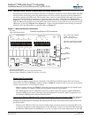
The IB2 board provides eight (8) programmable alarm relays with Form-C contacts. Default relay
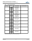
assignments are documented in Table 4. A blank column in Table 4 is also provided if you want to
document a custom configuration. Alarm relay contacts are rated for 2A @ 30VDC and 0.5A @
125VAC (60W maximum power consumption).
• Each relay can be individually configured to activate for any system alarm condition.
• Refer to the NetSure ITM Operation Manual (Section 6047) for programming instructions.
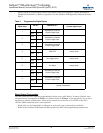
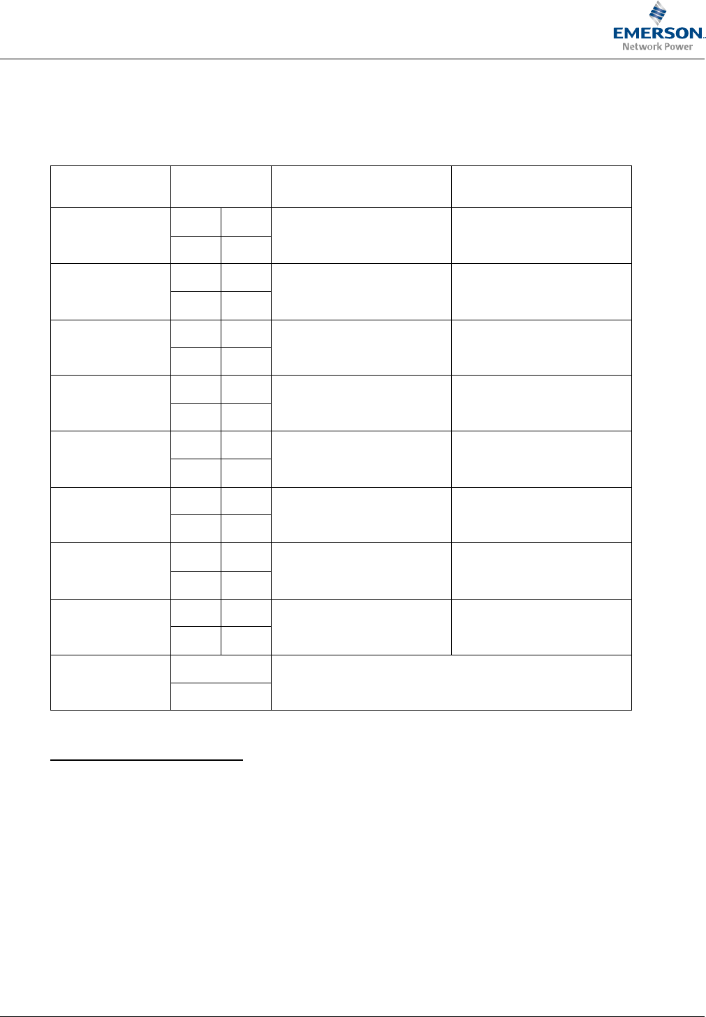
Table 3 Programmable Digital Inputs
Programmable
Digital Input
Pin No. Dedicated to...
Customer
Custom Digital Input
1
J3-1 –
Available for Customer
Custom Digital Input
J3-2 +
2
J3-3 –
Available for Customer
Custom Digital Input
J3-4 +
3
J3-5 –
Available for Customer
Custom Digital Input
J3-6 +
4
J4-1 –
PCU EPO factory wired
J4-2 +
5
J4-3 –
Fan Supply Alarm factory wired
J4-4 +
6
J4-5 –
Fan Alarm factory wired
J4-6 +
7
J5-1 –
Available for Customer
Custom Digital Input
J5-2 +
8
J5-3 –
Available for Customer
Custom Digital Input
J5-4 +
--
J5-5
internal connections
J5-6


