NetSure™ ITM with eSure™ Technology
Installation Manual, Section 6040 (Issue AB, April 8, 2013)
Spec. No: 582145500
44
Section 6040
Model: NetSure™ ITM Issue AB, April 8, 2013
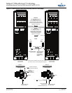
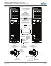
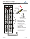
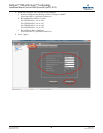
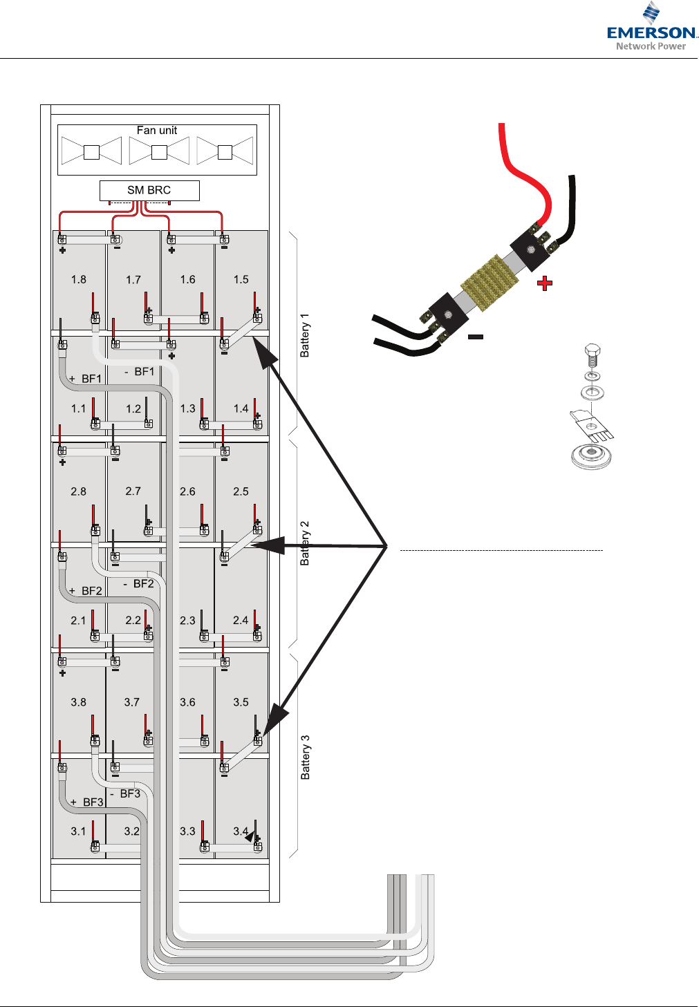
Figure 28 Making Final Battery Shelf Battery Interconnect Link Connections
DC UPS Module Rear View (B attery Compartment)
Final Battery Shelf Interconnections
1) Connect supplied Battery Interconnect
Links between these points.
2) Place faston lugs with factory wired
battery monitoring leads on top of
interconnect link as shown in illustration.
DO NOT PLACE BETWEEN LINK AND
BATTERY TERMINALS.
3) Torque to 97 in-lbs (11 Nm).
4) Place plastic cover over battery terminals
and interconnect links.
6) On all remaining battery terminals (factory
connections); remove the plastic covers,
check the torque, then reinstall the
plastic covers.
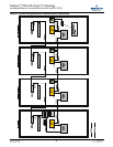
Bolt
Lock Washer
Typical Hardware Build-Up
Flat Washer
Faston
Lug
Battery
Interconnect
Link
Battery Terminal
Typical Monitoring
Lead Connections
Lead Labeled
1.5+ (Battery One Link)
2.5+ (Battery Two Link)
3.5+ (Battery Three Link)
Red
Monitoring
Lead
Black
Monitoring
Lead
Temperature
Sensor Lead
(white and
white/black
leads)
Faston
Lug
Faston
Lug
Battery
Interconnect
Link


