NetSure™ ITM with eSure™ Technology
Installation Manual, Section 6040 (Issue AB, April 8, 2013)
Spec. No: 582145500
30
Section 6040
Model: NetSure™ ITM Issue AB, April 8, 2013
IB2 Board DIP Switch Settings (for reference only)
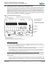
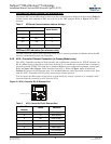
Dip Switch SW1 on the IB2 board is used to set the communications address for this board (Table 5).
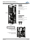
In this system, both switches of SW1 are to be set in the OFF position. Refer to Figure 17 for SW1
location.
Table 5 IB2 Board Communications Address Settings
IB2 Board LED Indicators (for reference only)
The IB2 board has a green LED indicator which is lit in normal operation and flashes when the IB2
board is communicating with the Controller.
4.4.6 ACU + Controller Ethernet Connection (to Primary Module only)
The ACU+ Controller provides a Web Interface via an Ethernet connection to a TCP/IP network. An
RJ-45 10BaseT jack is provided on the front of the ACU+ Controller for connection into a customer's
network running TCP/IP. This jack has a standard Ethernet pin configuration scheme, twisted pair.
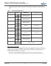
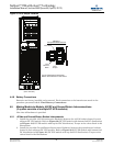
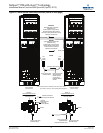
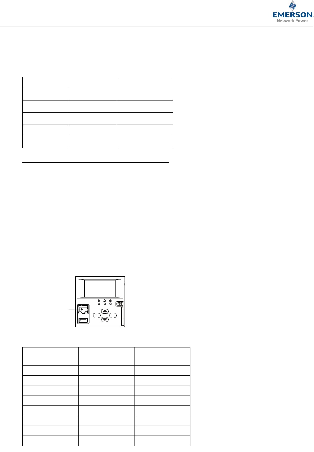
Refer to Figure 10 or Figure 11 for location of the ACU+. Refer to Figure 18 for location and
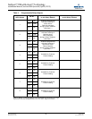
Table 6 for pinouts of the Ethernet port. Use shielded Ethernet cable (grounded at both ends). Note
that the ACU+ Controller’s RJ-45 jack is connected to chassis ground.
You can access the Web pages of the power system locally by using a "crossover" or "straight" cable
connected directly between your PC and the ACU+.
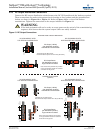
Figure 18 ACU+ Controller RJ-45 Ethernet Port
DIP Switch SW1
Board Number
1 2
OFF OFF 1
ON OFF 2
OFF ON 3
ON ON na
Table 6 ACU+ Controller RJ-45 Ethernet Port
Port Pin
Number
Name Definition
1 Tx+ Write Signal +
2 Tx- Write Signal -
3 Rx+ Read Signal +
4 -- no connection
5 -- no connection
6 Rx- Read Signal -
7 -- no connection
8 -- no connection
ESC ENT
Ethernet Port (RJ-45)


