NetSure™ ITM with eSure™ Technology
Installation Manual, Section 6040 (Issue AB, April 8, 2013)
Spec. No: 582145500
31
Section 6040
Model: NetSure™ ITM Issue AB, April 8, 2013
4.4.7 Optional Emergency Power Off (EPO) Connection (to Primary Module only)
The DC UPS module has an Emergency Power Off (EPO) function operated by a remote contact
provided by the User.
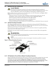
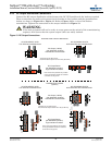
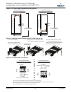
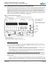
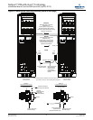
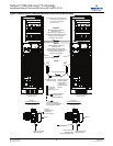
If the EPO function is desired, locate the EPO jumper in the Primary Module (see Figure 19).
Remove the EPO jumper (the jumper connects from the bottom terminal of the EPO terminal block
and the bottom of EPO Fuse F11). Connect a customer provided external normally closed switch
between the bottom terminal of the EPO terminal block and the bottom of the EPO Fuse.
The following occurs when the EPO switch is opened.
• The battery LVD contactor in each DC UPS module opens, disconnecting the battery from each
module.
• If the ACU+ "EPO Enabled" option is set to YES, the PCUs in each DC UPS module shut down
after 5 seconds. If the ACU+ "EPO Enabled" option is set to NO, PCUs remain running.
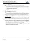
!
WARNING
The EPO circuit operates with -48Vdc. There is -48Vdc present on the terminals the EPO
jumper connects to. There is -48Vdc present on these same terminals that an external EPO
switch will be connected to.
NOTE
The external EPO switch wiring must be double-insulated. The wire must be 600V, 18-16 AWG
stranded for maximum runs between 82 and 197 feet (25-60m), respectively.
NOTE
The Emergency Stop action within the DC UPS module opens the battery LVD contactor and
(if programmed in the ACU+) shuts down the PCUs.
It does not internally disconnect the input power supply. To disconnect ALL power to the DC
UPS module, open the upstream feeder breaker(s) when the remote EPO is activated.
It does not disconnect the SM-BRC. The SM-BRC will still be powered by the batteries.


