NetSure™ ITM with eSure™ Technology
Installation Manual, Section 6040 (Issue AB, April 8, 2013)
Spec. No: 582145500
37
Section 6040
Model: NetSure™ ITM Issue AB, April 8, 2013
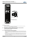
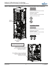
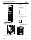
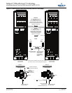
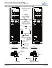
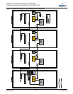
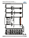
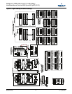
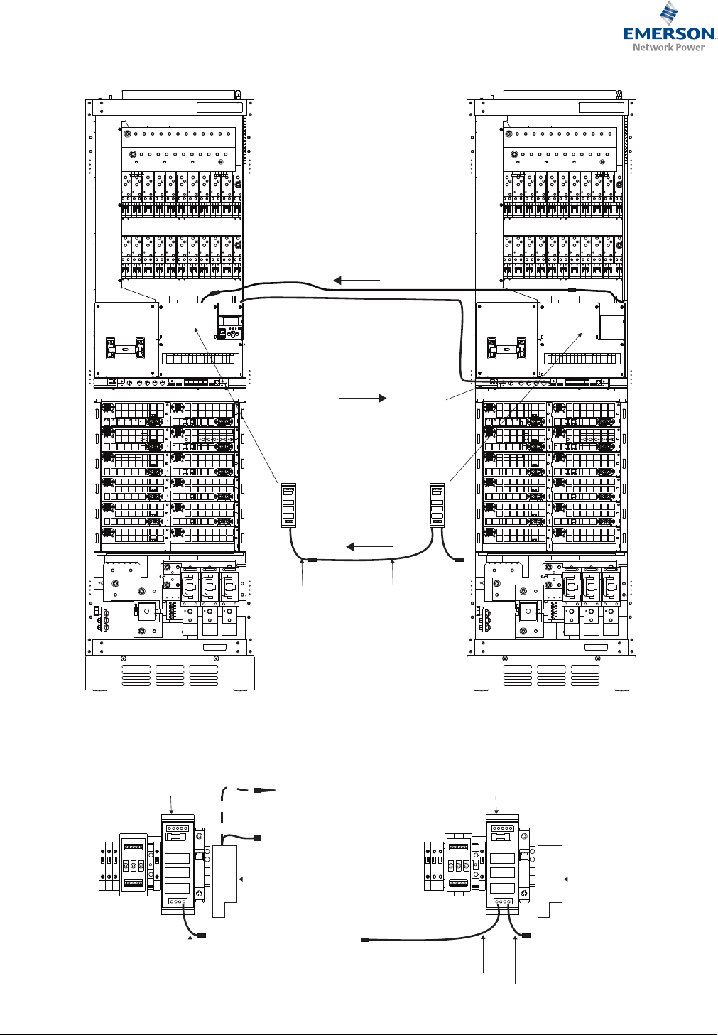
Figure 23 Alarm/Control Cable Interconnects (cont’d on next page)
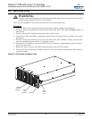
SUITA BLE F O R MO UNTI NG ON CONC RETE
OR O THER NO N-COM BUST IB LE SURF ACE O NLY.
Black/White Wire Twisted Pair
(RPM 628 351/1)
located coiled up on right side of
Expansion Module cabinet (mating
connector located behind Detail A cover)
Yellow/White Wire Twisted Pair
(RPM 628 415/2)
located coiled up on right side of
Primary Module cabinet (mating
connector located on SM-AC)
BLVD Control Cable
(RPM 628 465/3)
BLVD Control Cable
(RPM 628 466/3)
located coiled up
on right side of
Expansion Module
cabinets
Cable Runs this Direction
LVD
Relay
Board
LVD
Relay
Board
12
1 11
22
Front View
Primary Module
(door removed)
SEE DETAIL A
SUITA BLE F O R MO UNTI NG ON CONC RETE
OR O THER NO N-COM BUST IB LE SUR FACE O NLY.
12
1 11
22
Front View
Expansion Module
(door removed)
SEE DETAIL A
Note: Cabinets must be installed next to each other, shown
apart here for clarity of control cabling interconnections.
SM-AC
Cable Runs this Direction
Cable Runs this Direction
CAN-Bus
RS-485
BLVD
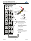
DETAIL A
Components Behind Cover
CAN-Bus
Black/White Wire
Twisted Pair
(Primary Module)
BLVD Control Cable
(RPM 628 465/3)
SM-DU+
LVD Relay Board
DETAIL A
Components Behind Cover
BLVD Control Cable
(RPM 628 466/3)
(Expansion Modules Only)
BLVD Control Cable
(RPM 628 465/3)
SM-DU+
LVD Relay Board
Can-Bus End Resistor
(if no Expansion Module)


