NetSure™ ITM with eSure™ Technology
Installation Manual, Section 6040 (Issue AB, April 8, 2013)
Spec. No: 582145500
43
Section 6040
Model: NetSure™ ITM Issue AB, April 8, 2013
6.0 S
TART
-U
P
I
NSTRUCTIONS
6.1 General
The NetSure ITM DC UPS system must be fully installed and commissioned before startup. The
start-up procedure consists of making final battery connections, initially starting the system, and
verifying system operation. Emerson Network Power will perform ALL start-up procedures, including
making final battery connections.
THE FOLLOWING ARE GENERAL GUIDELINES FOR EMERSON TECHNICIANS.
6.2 Final Battery Connections
6.2.1 Introduction
Each DC UPS module contains a battery compartment. The battery compartment consists of six
battery shelves that house (4) 6V batteries, each. Batteries are factory installed and wired for (3)
-48VDC battery strings. Also provided is a 800A battery disconnect fuse for each string.
6.2.2 Safety
Special care should be taken when working with the batteries associated with the DC UPS module.
See the precautions in the battery instruction manual and in Battery Compartment Precautions
at the beginning of these instructions.
6.2.3 Connecting Batteries
Battery Leads
The batteries are factory installed and most battery interconnections are factory made. The following
interconnections need to made during installation to complete the battery electrical path to the DC
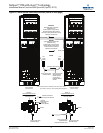
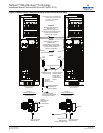
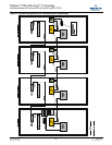
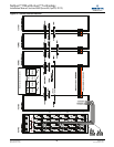
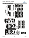
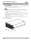
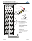
UPS module. Refer to Figure 28 for the battery connections torque value for the Emerson EB4 6V200
battery.
1. Refer to Figure 28 and connect the supplied Battery Interconnect Links between the indicated
Battery Shelves. For each connection:
a. Install the faston lugs on top of the battery links as shown in Figure 28. Note that battery
monitoring leads are factory connected to the faston lugs and each faston lug is insulated for
shipping. Observe proper polarity when attaching the faston lugs with factory wiring to the
battery posts.
b. Tighten the connections to the torque indicated in Figure 28.
c. Place the plastic cover over the battery terminals and interconnect link.
2. On all remaining battery terminals (factory connections); remove the plastic covers, check the
torque, then reinstall the plastic covers. Torque to value indicated in Figure 28.
DO NOT INSTALL THE BATTERY FUSES BEFORE THE EQUIPMENT HAS BEEN
COMMISSIONED AND THE PROCEDURE IN "6.3.1 - Initially Starting the DC UPS System
and Verifying System Operation" IS PERFORMED.


