TDM Interface: The Management Data Interface (MDI)
10002367-02 PmT1 and PmE1 User’s Manual
6-7
THE MANAGEMENT DATA INTERFACE (MDI)
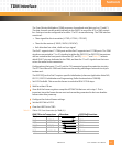
The MDI or Management Data Interface is a 3-wire protocol which allows access to the mod-
ule resources, registers and interrupts using the minimum resources necessary. This inter-
face consists of Data (MDIO), Clock (MDCLK) and Interrupt (MDINT) lines.
The MDI uses control pins PC0-PC2, which are not likely to conflict with any MPC860P dedi-
cated functions.
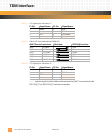
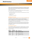
Table 6-6: MDI Port Connections
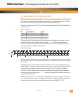
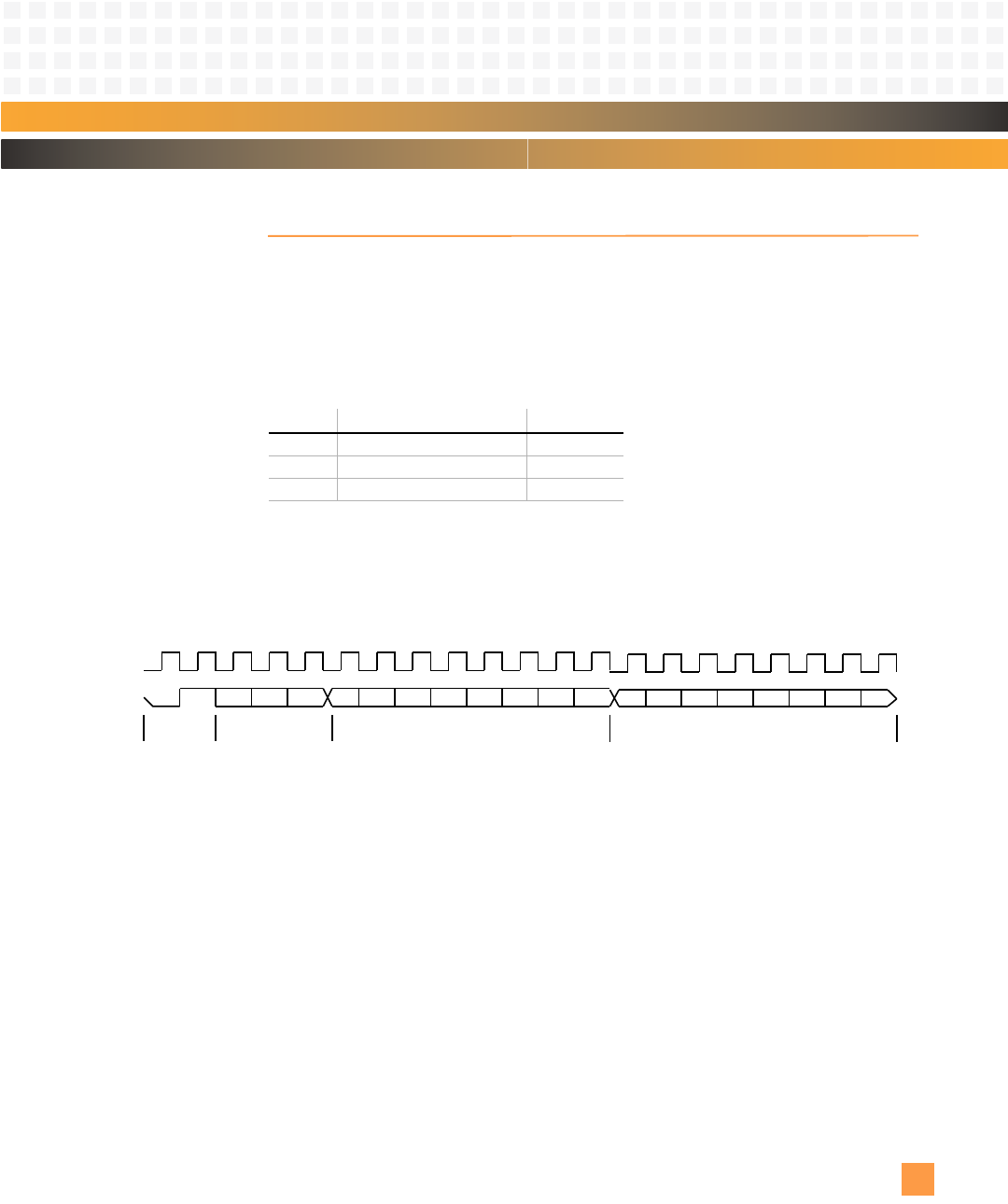
The protocol used to communicate involves sequencing bit patterns to indicate the start,
command, address, data and close of a transaction.
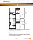
Fig. 6-2 shows how the interface is
accessed. This protocol is modeled after the existing standards for serial ROM and other
micro-wire type non-volatile memory devices.
Figure 6-2: MDI Interface Protocol
Note: The MDI interrupt line (MDINT) connects to the MPC860P at PC(15), which must set up as an active low (high-
to-low transition) interrupt. Consult the MPC860 PowerQUICC™ User’s Manual for details on configuring the
port C interrupt.
The MDI interface is intended for very low bandwidth communications and/or power up
configuration. The opcode specifies whether a read, write, or reset cycle is to take place. The
register address and data are written to and read from the PmT1 and PmE1 modules.
The PmT1 and PmE1 MDI provides the ability to identify the module, monitor interrupts,
and access the serial configuration.
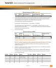
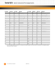
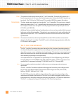
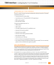
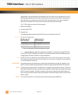
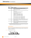
Ta ble 6 -7 provides the protocol format for communicat-
ing with the MDI interface.
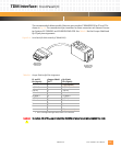
For MDI example code, contact an Emerson Network Power Technical Support representa-
tive: visit http://www.emersonembeddedcomputing.com/contact/postsalessupport.html
on the Internet, send e-mail to support@artesyncp.com, or call (800) 327-1251.
Pin: Description: Port:
MDINT MDI Interrupt Request PC(15)
MDC MDI Clock PC(14)
MDIO MDI I/O Pin PC(13)
CA D01 CC AAA AAAA DDDDDDD
MDC
MDIO
Start
Register Data (8 Bits)Register Address (8 Bits)
Opcode (3)


