10002367-02 PmT1 and PmE1 User’s Manual
8-1
Section 8
Monitor
The PmT1 and PmE1 monitor consists of a set of about 150 C language functions. The mon-
itor commands constitute a subset of these functions and are designed to provide easy-to-
use tools for PmT1 and PmE1 configurations at power-up or reset and communications,
downloads, and other common uses.
This chapter includes an introduction to monitor operation, instructions for command
sequences that configure the PmT1 and PmE1 modules, a command reference, and a func-
tion reference.
POWER-UP/RESET SEQUENCE
At power-up or board reset, the monitor performs hardware initialization, autoboot proce-
dures, free memory initialization, and if necessary, invokes the command-line editor. In
more detail, monitor execution starts up as follows.
1 The MPC860P is initialized first: caches are disabled, the memory control UPM (user-
programmable machine) is initialized, CS (chip select) memory map and control are
initialized, and the Systems Interface Unit (SIU) is initialized.
2 The QUICC sections are initialized in the following order: the NVRAM clock and data bits,
and then the console port SMC1.
3 The NVRAM is checked for functionality and valid contents (i.e., this is not the first power
up). If NVRAM is not valid, power-up diagnostics are run. If NVRAM is valid, the
PowerUpDiags bit is checked to see if diagnostics should be run. (Refer to Step 6 for a
description of the default NVRAM configuration parameters including PowerUpDiags.) If
PowerUpDiags is off, the system level initialization is performed.
4 Power-up Diagnostics: “Hello World” is printed on the console. Memory size is read from
the configuration register and printed on the console. The decrementer and timebase timer
is checked for functionality. The character sequence “89ABCDEF” is printed to test the print
hex ASCII routine. A Write/Read test is performed at location 0x40000. 0x05050a0a and its
complement is written and read. Then an address boundary test is performed.
5 System level initialization sets up the system for running compiled C code. BSS is cleared.
The dynamic data section is relocated from ROM to its linked address space starting at
0x2000. The RAM-based interrupt vector table is initialized. The interrupt prefix is changed
to point to the RAM-based interrupt table at 0x00000000. The stack is initialized at 0xFFF8.
All interrupt vectors in the interrupt vector table are initialized to use the unexpected
interrupt handler. This handler prints the message “Unexpected Interrupt” and restarts the
monitor. Masking of interrupts is reinforced. The memory parameters for system memory
management (e.g., Malloc) are initialized. If PowerUpDiags is set, the C code power-up
tests are run. The EEPROM test is run, and if IsModConfig is set, the PCI bus is configured
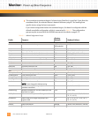
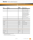
(see
Tab le 8 -1 ).


