PMC/PCI Interface: PCI Interrupts
PmT1 and PmE1 User’s Manual 10002367-02
7-8
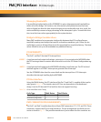
Managing Bandwidth
It is possible to inadvertently set the PCI9060ES to give a disproportionate bandwidth on
either side of the bridge. For instance, one side may retry frequently because the timer
value is slightly less than the time required to gain access to the other side. As a result, the
retries needlessly consume a large percentage of the attempted cycles. To avoid this situa-
tion, tune the timer values appropriately for the system devices.
Bridge to Bridge Considerations
Many PMC modules also incorporate a bridge chip between their PCI and local busses,
essentially creating two bridges that must be crossed to complete a cycle. Often, the sec-
ond bridge is a source of long delays due to the associated bus acquisition latency. The timer
values should be set up to accommodate any additional latency.
PCI INTERRUPTS
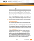
The PmT1 and PmE1 has two PCI interrupt lines:
LSERR*: A synchronous level output indicating a system error. It is asserted to the MPC860P when
the PCI bus target abort or master abort status bit is set in the PCI Status Configuration reg-
ister.
LINT0*: A synchronous level output to the MPC860P indicating a local interrupt. The PCI-to-local
doorbell register or a PCI BIST interrupt can generate a local interrupt.
See the PCI9060ES data sheet for more details on the interrupt lines. CPU Interrupts
describes the interrupt handling by the MPC860P.
PCI Bus Interface
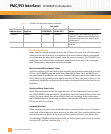
Using the DRAM timing, the PCI interface of the PmT1 and PmE1 is capable of the transfer
rates given in
Tab le 7 -8 . The transfer rates to PCI bus are dependent on the baseboard
design. Local to PCI bus and PCI to local bus does not support bursting.
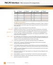
Table 7-8: PCI-to-Local Slave Access Timing
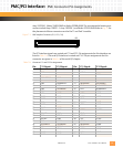
PMC CONNECTOR PIN ASSIGNMENTS
The PmT1 and PmE1 modules have three 64-pin PMC connectors: P11, P12, and P14. These
connectors support the PCI and serial interfaces. The pin arrangement for the 64-pin con-
nector is shown in
Fig. 7-1. The possible manufacturer part numbers for this connector are
Cycle Type: Wait States: Total Clocks:
Slave Read (long word) 1 5
Slave Write (long word) 1 5


