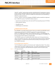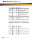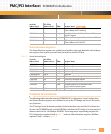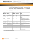
PMC/PCI Interface: PCI9060ES Initialization
10002367-02 PmT1 and PmE1 User’s Manual
7-3
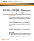
Shared Runtime Registers
The Shared Runtime registers are a collection of mailbox, interrupt, doorbell, and configura-
tion registers that may be accessed from the local bus and the PCI bus.
Table 7-3: Shared Runtime Registers
PCI9060ES INITIALIZATION
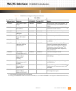
The following tables describe how the PCI9060ES PCI Configuration, Local Configuration,
and Shared Runtime registers are initialized to set up the PCI bridge and turn on the neces-
sary functions.
The PCI bridge is used to decode portions of the local address bus and the PCI address bus.
At reset, the PCI9060ES reads a serial EEPROM to initialize the PCI bridge. Five long words of
data are stored in the 128-kilobyte EEPROM. These long words sequentially program the
PCI Configuration registers listed in
Tab le 7 -4 and two Shared Runtime registers–Mailbox
registers 0 and 1–listed in
Ta bl e 7 -6.
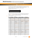
C100,00A0 20 Long Local Bus Base Address register
(Direct Master to PCI memory)
C100,00A4 24 Long Local Base Address For Direct Master to PCI
I/O/CFG register
C100,00A8 28 Long PCI Base Address register (Direct Master to PCI)
C100,00AC 2C Long PCI Configuration Address register
(Direct Master to PCI IO/CFG)
Local Bus
Address (hex)
:
PCI Offset
Address (hex):
:Size: Register Name:
C100,00C0 40 Long Mailbox register 0
C100,00C4 44 Long Mailbox register 1
C100,00C8 48 Long Mailbox register 2
C100,00CC 4C Long Mailbox register 3
C100,00D0-DF 50-5C — reserved
C100,00E0 60 Long PCI to Local Doorbell register
C100,00E4 64 Long Local to PCI Doorbell register
C100,00E8 68 Long Interrupt Control/Status
C100,00EC 6C Long EEPROM Control, PCI Command Codes,
User I/O & Init Control register
C100,00F0 70 Long PCI Configuration ID register
Local Bus
Address (hex)
:
PCI Offset
Address (hex):
Size: Register Name: (continued)


