PMC/PCI Interface: PCI9060ES Initialization
PmT1 and PmE1 User’s Manual 10002367-02
7-6
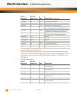
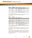
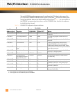
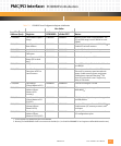
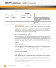
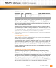
Table 7-6: PCI9060ES Shared Runtime Register Initialization
Deadlocked Cycles
When a local bus master attempts to access the PCI bus at the same time a PCI bus master
attempts to access the local bus, a deadlocked cycle results. Neither master can complete
its cycle because the other device already owns the required resource. The PCI9060ES can
quickly force one of the masters to relinquish ownership of its bus and try the cycle again
later. Consequently, retrying one side favors the other.
Retries on Local Direct Master Cycles
Local Direct Master cycles are transfers that originate from a local bus master and access the
PCI bus. The PCI9060ES programmable Direct Slave BREQo Delay Timer and BREQo retry
pin control Local Direct Master cycle retries. If enabled, this timer counts down when a Local
Direct Master cycle is pending and unable to access the PCI bus. If the count expires, a true
condition on the BREQo pin signals the local master to relinquish the local bus and retry its
cycle later.
Retries on Direct Slave Cycles.
Direct Slave cycles are transfers that originate from a PCI bus master and access the local
bus. The PCI9060ES programmable PCI Target Retry Delay Timer controls Direct Slave cycle
retries. This timer counts down while a Direct Slave cycle is pending. If the count expires,
the PCI9060ES signals a “target retry” condition, informing the PCI master to relinquish the
PCI bus and retry its cycle later.
Assigning Priorities
When assigning a bus priority for deadlocked cycles, consider whether a series of transfers
on one side of the bridge could starve access on the other side. Also, consider whether there
may be other adverse effects of retrying Local Direct Master cycles or Direct Slave cycles.
The following PCI9060ES internal register fields control bus priority and also are accessible
from the PmT1 and PmE1 monitor (see
Tab le 8 -1 ).
Hex Value
Local Bus
Address (hex): Register:
at the
PCI9060ES:
byte-swapped
at the CPU: Notes:
C100,00C0 Mailbox 0 00000000 00000000 These registers are initialized by the serial
EEPROM. C10000C0 will be a5000000 upon
successful completion of the Monitor power
up diagnostics.
C100,00C4 Mailbox 1 00000000 00000000 These registers are initialized by the serial
EEPROM.


