


Installing a VHSIM
Installation 2-11
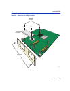
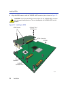
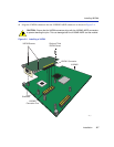
8. Press down firmly on the back of the VHSIM2-A6DP until the pins slide all the way into the
connector holes.
9. Secure the VHSIM2-A6DP to the faceplate using the two screws saved in step 5.
10. Secure the VHSIM2-A6DP to the standoffs with the two screws saved in step 6.
11. Reinstall the interface module in the chassis.
12. Reattach the network cabling to the interface module.
13. Refer to Chapter 3 for instructions on configuring the VHSIM2-A6DP using Local
Management.
2.4.2 Installing a VHSIM2-A6DP in a Standalone Device
To install a VHSIM2-A6DP into a standalone device that supports VHSIM2-A6DP technology,
perform the following steps:
1. Power down the device and remove the power cord.
2. Disconnect all cables from the device. Note the ports to which these cables attach.
3. Attach the antistatic wrist strap (refer to the instructions outlined on the antistatic wrist strap
package).
4. Remove the device chassis cover (refer to your specific device documentation for instructions
on removing the device chassis cover).
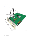
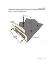
5. Remove and save the two faceplate mounting screws securing the VHSIM2-A6DP coverplate
and remove the coverplate as shown back in Figure 2-5.
6. Remove and save the two standoff screws as shown back in Figure 2-5.
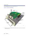
CAUTION: Ensure that the VHSIM2-A6DP connectors align with the host device
connector pins to prevent bending the pins. This can damage both the VHSIM2-A6DP
and the module.
CAUTION: In step 10 ensure that the standoffs on the interface module align with the
standoff screw holes on the VHSIM2-A6DP to prevent bending the pins.
ELECTRICAL HAZARD: Ensure that you remove the power cord and ONLY the screws
required to remove the chassis cover. Failure to comply could result in an electric shock
hazard.