


C-3
Serial Line Replacement
• Destination Address. This address tells the Ethernet Adapter where to send data
received on the serial port. You may enter the RMP address of another Ethernet
Adapter for direct serial line replacement. Other possible values are “dynamic” or
“broadcast”. Entering “dynamic” causes data to be sent to the Ethernet Adapter from
which the unit last received data. Using the value of “dynamic” is an easy way to allow
two Ethernet Adapter units that are by themselves to communicate to each other.
Entering “broadcast” causes the data to be sent to all Ethernet Adapter devices set to
use RMP Pipe.
• Transmit Try Count. For non-broadcast data, this count specifies the number of
attempts that the Ethernet Adapter should make in transmitting each RMP packet of
data. A transmission attempt may fail if the destination Ethernet Adapter is out of range
or turned off. When this happens, the data will be lost if retry attempts are not made,
or are not successful. The Transmit Try Count gives the user the ability to tell the
Ethernet Adapter how diligently to attempt transmission of data. Note that subsequent
RMP data transmissions are delayed until the packet being retried is successfully sent,
or the maximum try count is reached. The maximum count is 65000 times. The default
value is “infinite,” which causes each packet to be retried until successfully sent. Select
the Transmit Try Count based on the sensitivity of your application to data delay and/
or data loss:
• Transmit Retry Interval. When making additional transmit attempts as specified
with “transmit try count” above, it is necessary to specify how long to wait between
successive retry attempts. This setting determines the time period between
retransmission attempts. The value is specified in 1/100ths of a second, so that a value
of 100 means 1 second. The maximum value is 65000. The default value is 100.
• I/O Control. I/O control is only relevant to serial line replacement applications that
use the RMP protocol. I/O control defines control over digital inputs and outputs of the
Ethernet Adapter separately from the data lines. Digital input and output are shared
with the flow control lines (RTS, DTR, CTS, and DSR). In this mode the Ethernet
Adapter does not interpret them as flow control signals. They provide the ability to
send digital data from one device to another without interpretation by the Ethernet
Adapters themselves. When an Ethernet Adapter detects a change in one of its RTS or
DTR lines, it will cause the opposite Ethernet Adapter to immediately change the state
of its corresponding CTS or DSR line to match. You can not use Hardware Flow
control on lines that have been enabled for I/O Control.
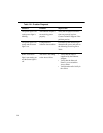
Application Sensitivity Transmit Try Count Setting
Sensitive to data delay Low transmit try count
Sensitive to data loss High transmit try count