


EPSON Stylus C63/64/83/84 Revision A
Disassembly and Assembly Disassembly 15
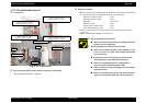
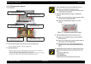
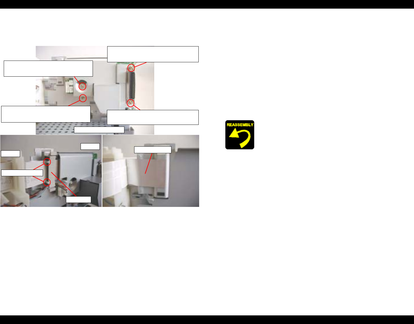
1.3.3 Circuit board removal
o External view
Figure 1-4. Circuit board
o
Part/Unit that should be removed before removing Circuit board
Housing (Right/Left/Frame) / ASF unit
o Removal procedure
1) Remove Clamp core from [Mounting Plate, M/B], and disconnect the following
seven cables from the corresponding connectors on main board.
- CR motor connector cable : CN5
- PF motor connector cable : CN6
- Head FFC : CN7, CN8
- PE sensor cable : CN9
- Power supply connect cable : CN2
- Panel board connector cable : CN4
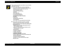
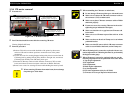
2) Remove four screws for securing Circuit board to main frame, and remove
the board.
3) Remove [Shield Plate, M/B] from main board.
Screw type : C.B.S TITE SCREW, 3x14, F/SN
Order of tightening : First
Thghtening torque : 8
±
1 kgf.cm
Screw type : C.B.S TITE SCREW, 3x10, F/SN
Order of tightening : Third
Thghtening torque : 8
±
1 kgf.cm
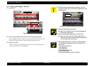
Screw type : C.B.S TITE SCREW, 3x14, F/SN
Order of tightening : Second
Thghtening torque : 8
±
1 kgf.cm
Screw type : C.B.S TITE SCREW, 3x6, F/SN
Order of tightening : 4th
Thghtening torque : 8
±
1 kgf.cm
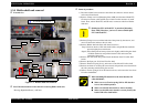
Main board (Backside)
HP side
Far side
Dowel of cramp core
Shield Plate FFC
Cramp core
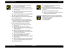
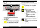
o When assembling Circuit board,
n Make sure that the metal fittings for locking the Parallel
interface is on its shield plate.
o When assembling Circuit board to main frame,
n Make sure to connect all cables to the connectors (CN2,
CN4, CN5, CN6, CN7, CN8, CN9) on main board in the
correct direction.
n Fasten four screws for securing Circuit board in the
order/tightening torque indicated in the figure.
n Make sure that Shield plate FFC on Head FFC is
securely pasted on [Mounting Plate, M/B].
n Make sure that two dowels of Clamp core is set in home
position direction.
n Make sure that PE sensor cable & CR motor connector
cable are set on Holder shaft unit, and in Clamp core.