


EPSON Stylus C63/64/83/84 Revision A
Disassembly and Assembly Disassembly 22
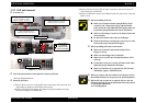
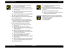
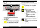
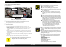
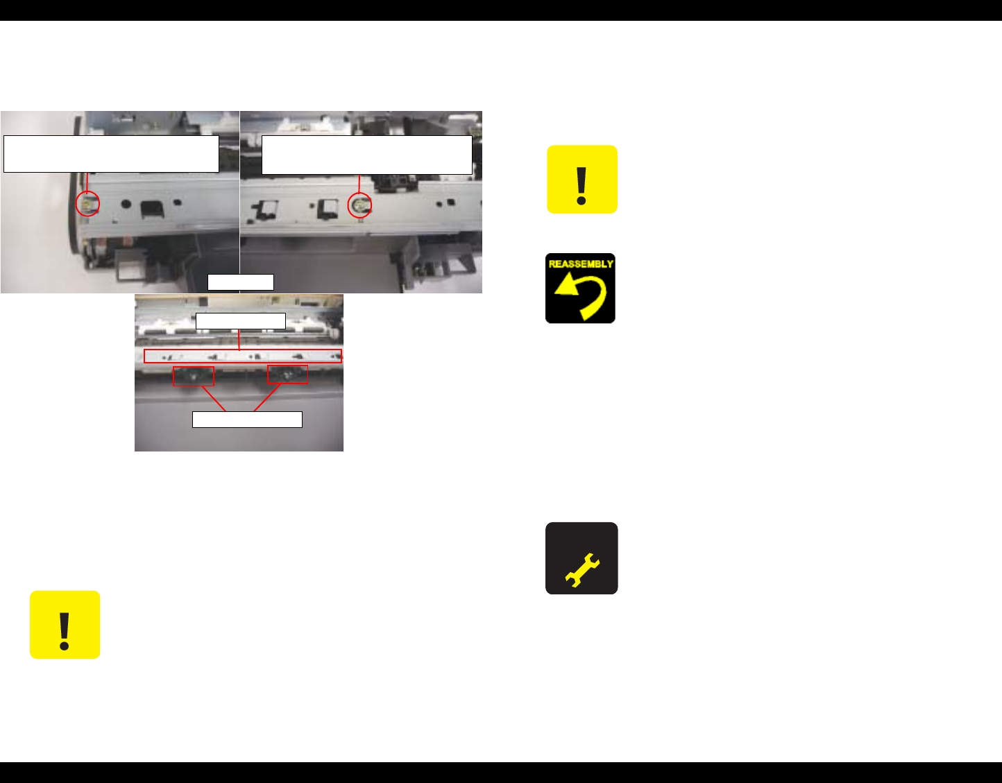
1.3.8 Front frame removal
o External view
Figure 1-11. Front frame removal
o
Part/Unit that should be removed before removing Paper guide front
Housing (Right/Left/Frame)
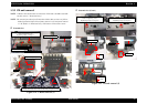
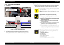
o Prcedure of removal
1) Return CR unit to home position before removing Front frame.
2) Remove two screws for securing Front frame to main frame.
3) Lift up the left side of Front frame slightly, and slide the frame toward the front
side of the printer.
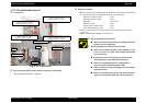
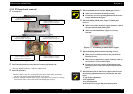
C A U T I O N
o The following procedure is only for Front frame removal.
In case that Front frame is removed for CR unit removal,
there is some added operations before Front frame removal.
As for the detailed procedure, refer to 1.2.7 "CR motor
removal".
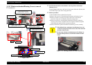
Screw type : C.B.S TITE SCREW, 3x6, F/ZN
Order of tightening : Second
Thghtening torque : 8
±
1 kgf.cm
Front frame
Star wheel holder
Star wheel eject holder
Screw type : C.B.S TITE SCREW, 3x6, F/ZN
Order of tightening : First
Thghtening torque : 8
±
1 kgf.cm
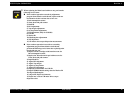
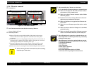
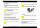
C A U T I O N
o Do not damage [Pulley, Eject, Driven] when sliding the
Front frame to the left side of the printer.
o When assembling Front frame to main frame,
n Make sure that the Star wheel holder & Star wheel eject
holder is correctly fixed.
n Make sure that the Star wheel moves smoothly.
n Fasten two screws for securing Front frame to main
frame in the order/tightening torque indicated in the
figure.
n Make sure that the CR unit moves smoothly.
n Make sure that there is no gap between Front frame
frame main.
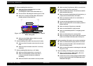
n Do not hold Front frame while handling printer
mechanism in your repair.
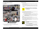
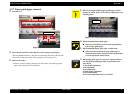
A D J U S T M E N T
R E Q U I R E D
o When you replace Front frame with new one, lubricate it
with the suitable amount of G-58 grease by the specified
position.
o When Front frame is removed or replaced with new one, the
following adjustment must be performed in the order below.
1) PF adjustment
2) Bi-d adjustment