


EPSON Stylus C63/64/83/84 Revision A
Disassembly and Assembly Disassembly 17
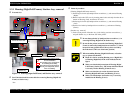
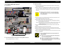
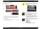
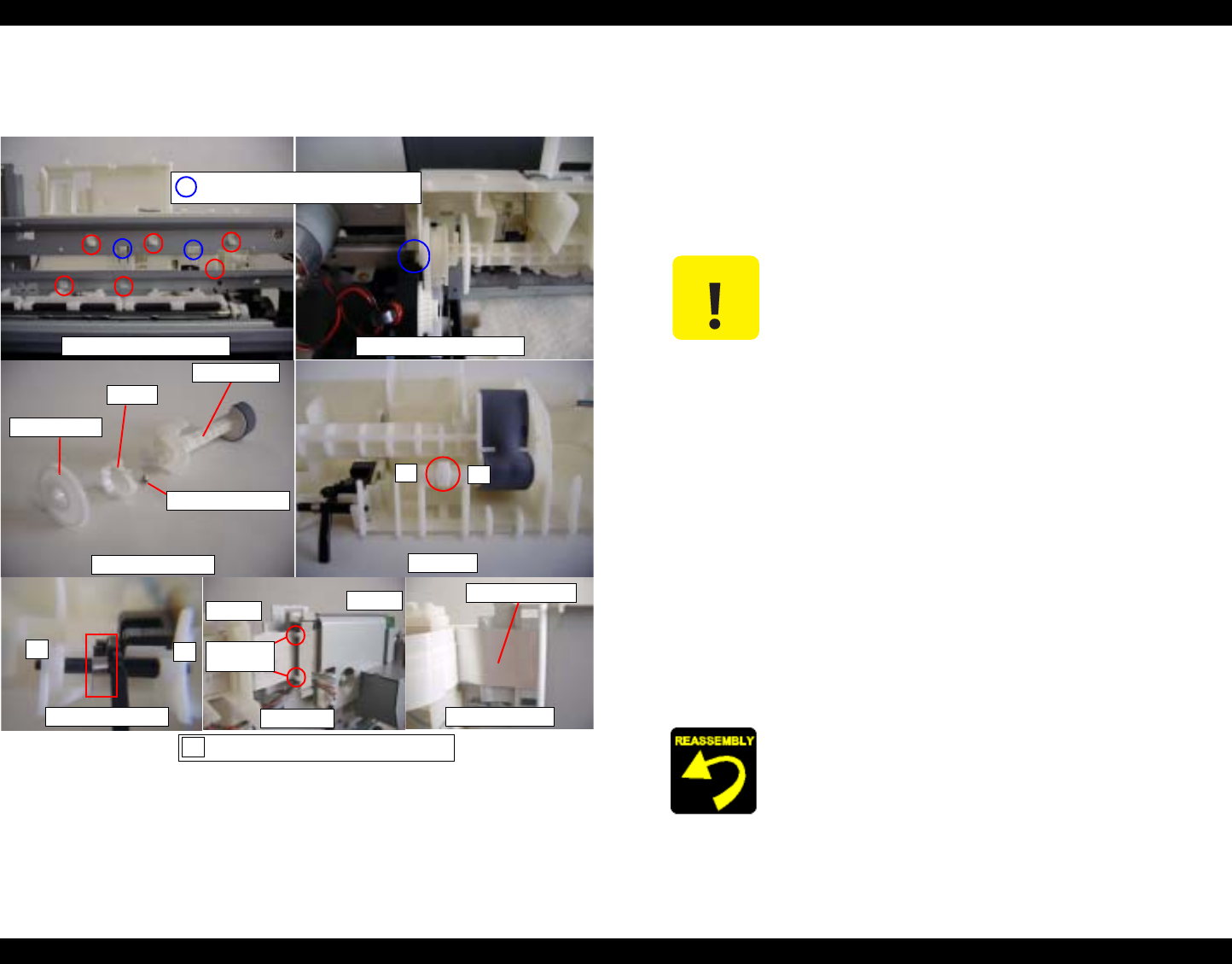
1.3.4 Holder shaft unit removal
o External view
Figure 1-5. Holder shaft unit removal
o
Part/Unit that should be removed before removing Holder shaft unit
Housing (Right/Left/Frame) / ASF unit
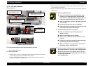
o Removal procedure
1) Disconnect Panel board connector cable from the connector on main board,
and remove Panel board.
2) Remove Clamp core from [Mounting Plate, M/B] and disconnect Head FFC,
CR motor connector cable and PE sensor cable from the connector on main
board. Then, release Head FFC and CR motor connector cable from Holder
shaft unit.
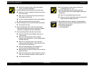
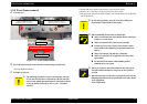
3) Release Change lever toward the backside of the printer by the tweezer, and
move CR unit to the leftmost side (far side).
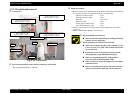
4) Remove Holder shaft unit from main frame as belows.
Step1) Push two hooks of LD roller shaft holder, and pull Holder shaft unit
upward slightly from main frame.
Stepe2) Move Pump unit to home position side slightly while holing the whole
of Holder shaft unit, and pull the bottom of the unit toward the
backside of the printer.
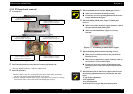
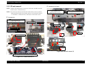
5) Remove LD roller shaft along with Clutch mechanism from LD roller shaft
holder.
6) Remove the Spur gear 36.8 from LD roller shaft.
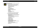
7) Remove Extension spring, 0.143, and remove Clutch from LD roller shaft.
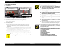
8) Release one hook for securing PE sensor board, and push the sensor board from
the side contacting main frame by the tweezer.
9) Release Torsion spring 0.22 for PE detection levers, and remove the lever from
LD roller shaft holder.
Holder shaft unit (Backside)
Holder shaft unit (Front side)
Idle roller
LD roller shaft unit
Torsion spring 0.22
Shield Plate FFC
Cramp core
HP side
Far side
Shield Plate FFC
Dowel of
cramp core
Spur gear 36.8
Clatch
Tension spring 0.143
LD roller shaft
This marking is the hook/protrusion
for releasing Holder shaft uni.
1
2
1
2
This marking is the order of assembling.
1
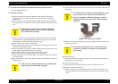
C A U T I O N
o Shield plate FFC on Head FFC is pasted on [Mounting
Plate, M/B]. Therefore, you have to remove Shield plate
FFC with Head FFC.
o When assembling PE detection lever & sensor board to LD
roller shaft holder,
n Make sure to set Torsion spring 0.22 for PE detection
lever to the suitable position.
n Make sure that PE detection lever moves smoothly.
n Make sure that PE sensor board is correctly fixed by the
hook of LD roller shaft holder.