


EPSON Stylus C63/64/83/84 Revision A
Disassembly and Assembly Disassembly 30
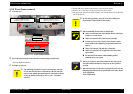
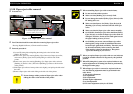
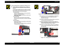
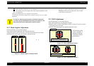
o When assembling Printer mechanism to Housing (Lower),
n On this models, the assembed accuracy of each part
composed of Printer mechanism is based on Housing
(Lower).
To ensure the assembled accuracy, you have to control
the assembled standard position of main frame against
X/Y/Z-axis direction as the following figure.
[X-axis direction]
- Make sure that main frame is correctly placed on
the groove of Housing (Lower).
- Make sure that there is no gap between main frame
and Housing (Lower).
[Y-axis direction]
Make sure that cut-out portion of main frame is
correctly placed on the square protrusion of Housing
(Lower).
[Z-axis direction]
- Make sure that there is no gap between main frame
and Housing (Lower).
- Make sure that the left side of Printer mechanism is
correctly fixed by two hooks.
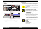
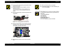
Figure 1-20.
Assembled standard
position of Y-axis
direction of main frame
Assembled standard
position of X-axis
direction of main frame
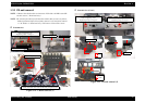
Figure 1-21. Assembled standard position of main frame
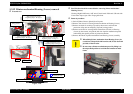
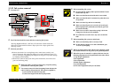
n
Fasten four screws for securing Printer mechanism to
Housing (Lower) in the order/tightening torque
indicated in the figure.
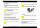
n Make sure that total seven [Porous Pad] is correctly set
in rib/cut-portion of Housing (Lower).
n Make sure that there is gap between the surface of
[Porous Pad, Ink Eject, Uppoer (Large)] and the surface
of [Porous Pad, Ink Eject, Uppoer (Small)].
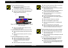
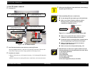
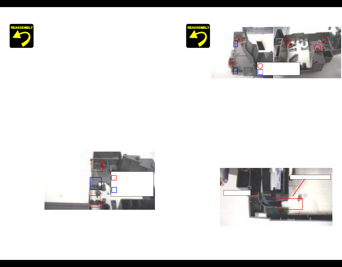
n Make sure to place ink tube on the groove of Housing
(Lower), and to set [Porous Pad, Tube Fasten] on the
end of ink tube.
Figure 1-22. Setting position of Ink tube (1)
Assembled standard
position of Z-axis
direction of main frame
Ink tube
Porous Pad, Tube Fasten