


EPSON Stylus C63/64/83/84 Revision A
Disassembly and Assembly Disassembly 33
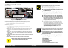
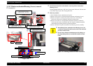
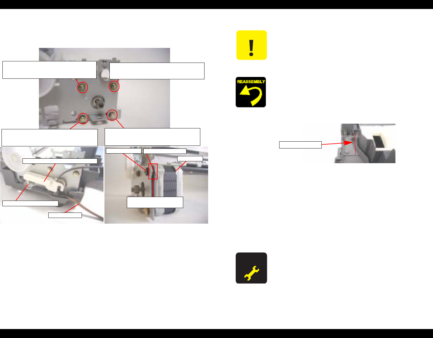
1.3.14 PF motor removal
o External view
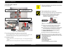
Figure 1-26. PF motor removal
o
Part/Unit that should be removed before removing PF motor
Housing (Right/Left/Frame) / ASF unit / Circuit board / PS board / CR unit with
Front frame / Paper eject roller / Paper guide front / Housing (Lower)
o Procedure of removal
1) Remove Idle roller assy. & Compression spring, 1.13 for keeping PF timing belt
tension.
2) Remove four nuts for securing PF motor to main frame, and remove the motor.
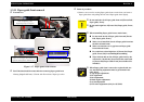
Idle roller assy. (Idle roller & holder)
PF timing belt
Compression spring, 1.13
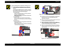
Screw type : HEXAGON NUT, NORMAL, M3
Order of tightening : First
Thghtening torque : 6
±
1 kgf.cm
Screw type : HEXAGON NUT, NORMAL, M3
Order of tightening : Second
Thghtening torque : 6
±
1 kgf.cm
Screw type : HEXAGON NUT, NORMAL, M3
Order of tightening : Third
Thghtening torque : 6
±
1 kgf.cm
Screw type : HEXAGON NUT, NORMAL, M3
Order of tightening : 4th
Thghtening torque : 6
±
1 kgf.cm
PF motor
Compression spring, 1.53
(This spring is only here)
Spacer, Insulator
Insurator, Motor, PF
C A U T I O N
o When removing PF motor from main frame, do not damage
the pinion gear of PF motor.
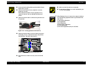
o When assembling PF motor to main frame,
n Do not damage PF motor pinion gear with main frame.
n Make sure to place PF motor connector cable to
Housing (Lower) properly before put printer
mechanism on Housing (Lower).
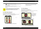
Figure 1-27. Placement position of PF motor cable
n
Make sure to connect PF motor connector cable to
connector (CN6) on main board by the tweezer.
n Fasten four nuts for securing PF motor to main frame in
the order/tightening torque indicated in the figure.
n Make sure that there is no gap between [Spacer,
Insulator] and frame main.
n Make sure not to lost Compression Spring, 1.53.
A D J U S T M E N T
R E Q U I R E D
o When PF motor is removed or replaced with new one, the
following adjustment must be performed in the order below.
1) Top margin adjustment
2) PF adjustment
3) Bi-d adjustment
4) Head angular adjustment
5) 1st dot adjustment
6) PW sensor adjustment (Only for SC83/84)
Placement position