


EPSON Stylus C63/64/83/84 Revision A
Disassembly and Assembly Disassembly 25
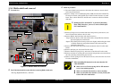
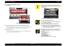
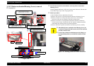
o When assembling Print head assy.,
n Make sure that the CR timing belt is set in the
assembling groove correctly.
(CR timing belt is under hook of Print head assy..)
n Do not stain the CR timing belt with the grease (G-58).
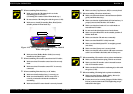
n Make sure to install [Grounding Plate, Head] in the
suitable position in Print head assy..
Figure 1-15. Setting position of Grounding Plate, Head &
Holer roller guide
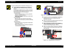
n
Make sure that [Holder Roller Guide] is correctly
installed as the above figure.
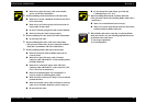
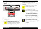
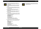
o When assembling CR encoder sensor board to IC holder,
n Make sure that CR encoder sensor board is correctly
fixed.
n Make sure that CR encoder sensor FFC is correctly
connected.
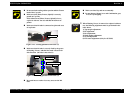
o When assembling Print head assy. to IC holder,
n Make sure that Print head assy. is correctly set.
n Make sure that Head FFC & PW sensor FFC is
correctly connected with interim condition in
assembling.
n Make sure that PW sensor board is correctly located.
Grounding Plate, Head
Holer roller guide
Main frame
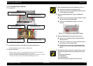
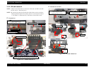
n Make sure that [Cap, Detector, PW] is correctly fixed.
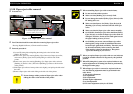
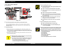
o When assembling CR unit to main frame,
n Make sure that main frame is located between [Roller
guide] and Print head assy..
n Make sure that the right/left hook of Print head assy. is
properly inserted into the hole of IC holder.
n Make sure that four hooks of Cover cable head are
inserted into IC holder.
n Do not touch the lubrication area of main frame.
n Make sure place Head FFC on the suitable position of
Holder shaft unit.
n Make sure that the CR unit moves smoothly.
n Make sure that Head FFC is fully inserted.
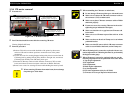
n Make sure that Shield plate FFC is straightly pasted.
(not slant.)
n Make sure that Clamp core is securely fixed.
n Make sure that PE sensor cable & CR motor connector
cable is set on Holder shaft unit, and in Clamp core.
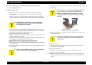
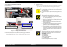
o When assembling CR encoder scale to printer mechanism,
n Make sure that Extension spring 1.494 is not twisted.
n Make sure that CR encoder scale is inserted between
ribs of CR encoder sensor.
n Make sure that CR encoder is not damaged, or dirt with
the grease (G-58).
o When assembling CR timing belt to printer mechanism,
n Make sure that [Stopper, Holder Pulley, Driven] is
installed into dowels of main frame.
n Fasten one screw for securing [Stopper, Holder Pulley,
Driven] to main frame in the order/tightening torque
indicated in the figure.