


EPSON Stylus C63/64/83/84 Revision A
Disassembly and Assembly Disassembly 24
o
Part/Unit that should be removed before removing CR unit removal
Housing (Right/Left/Frame)
o Removal procedure
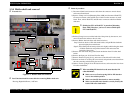
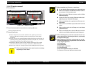
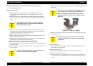
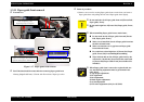
1) Release CR lock lever toward the backside of the printer by the tweezer,
and move CR unit from home position to around the center of the printer
mechanism.
2) Remove Clamp core from [Mounting plate, M/B], and disconnect Head FFC
from the connector on main board. Then, release Head FFC from Holder shaft
unit.
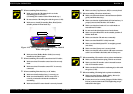
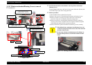
3) Loosen one screw for securing Stopper holder pulley driven to main frame &
CR timing belt by pushing Driven pulley holder to the right side, and release
CR timing belt carefully from CR motor pinion gear.
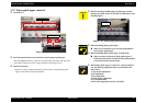
4) Remove CR encoder scale from main frame.
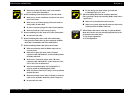
5) Release one hook for securing Cover cable head to CR unit, and remove Cover
cable head with pushing it down .
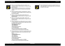
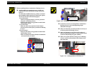
6) Release two hooks for securing IC holder to Print head assy.by the tweezer, and
pull IC holder until the holder contacts Front frame.
7) Return CR unit to home position before removing Front frame.
8) Remove two screws for securing Front frame to main frame.
9) Lift up the left side of Front frame slightly, and slide the frame toward the front
side of the printer.
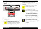
10) Move CR unit to the center of the printer mechanism with holding the whole of
the unit by hand.
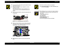
11) Pull IC holder slightly to the front side of the printer, and remove CR unit from
main frame.
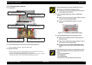
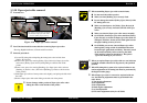
12) Release two hooks for securing [Cap, Detector, PW] to IC holder, and remove
[Cap, Detector, PW].
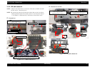
[Print head removal]
13) Disconnect Head FFC from the connectors on print head board, and remove
Print head assy. from IC holder.
[PW sensor board removal]
13) Disconnect PW sensor FFC from the connector of PW sensor board.
[CR encoder sensor board removal]
13) Release two hooks for securing CR encoder sensor board to IC holder, and
disconnect CR encoder senser FFC from the connector of CR encoder sensor
board.
C A U T I O N
o Shield plate FFC on Head FFC is pasted on [Mounting
Plate, M/B]. Therefore, you have to remove Shield plate
FFC with Head FFC carefully.
C A U T I O N
o Unless you held CR unit by hand, there is a possibility that
the nozzle surface of Print head is damaged.
C A U T I O N
o You cannot remove IC holder from Print head assy., if you
have to remove [Cover, Detector, PW] and Head FFC.
o There is a possibility of Head FFC damage by excessive
pulling toward the front of the printer without removing
Head FFC.
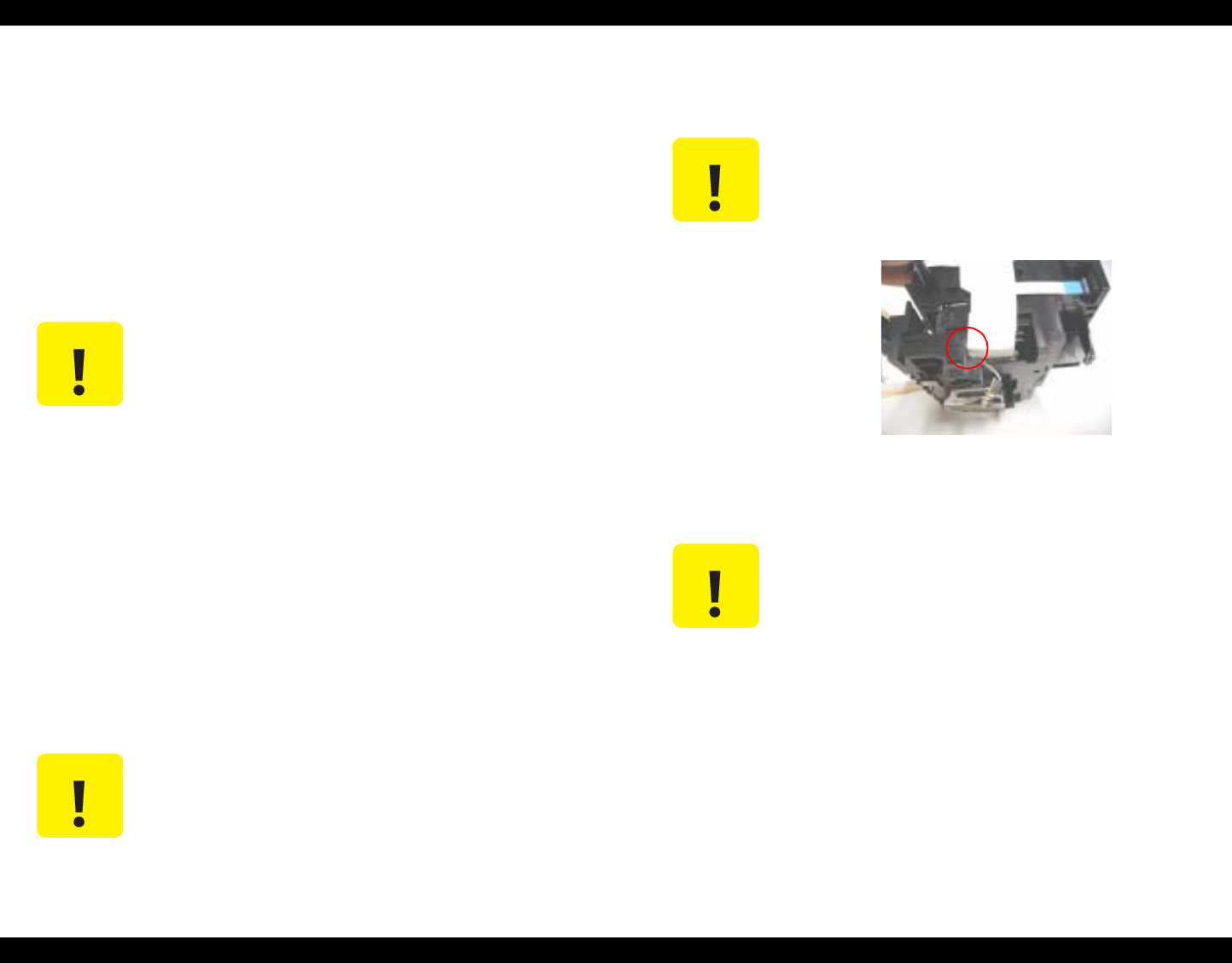
Figure 1-14. Head FFC removal
C A U T I O N
o In case that [Cap, Detector, PW] is removed, PW sensor
board is free. Therefore, be caureful not to damage PW
sensor board.