


EPSON Stylus C63/64/83/84 Revision A
Disassembly and Assembly Disassembly 18
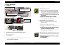
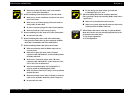
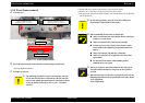
n Make sure to place PE sensor cable to the suitable
groove on LD roller shaft holder.
o When assembling Clutch mechanism to LD roller shaft,
n Make sure to set the round hole of Clutch on the dowel
of LD roller shaft.
n Make sure to set Tension spring 0.143 to the hooks of
Clutch and LD roller shaft.
n Do not set Tension spring 0.143 with twisted condition.
n Make sure that the Clutch rotates properly.
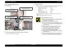
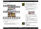
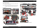
o When assembling LD roller shaft to LD roller shaft holder,
n Do not touch LD roller.
o When assembling Idle roller to LD roller shaft holder,
(This operation is done after all parts composed of Holder
shaft unit is assembled to LD roller shaft holder.)
o When assembling Holder shaft unit to main frame,
n Make sure that nine hooks of Holder shaft unit are
correctly fixed.
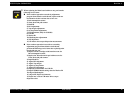
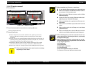
n Make sure to place PE sensor cable, CR motor
connector cable and Head FFC on the suitable position
of Holder shaft unit.
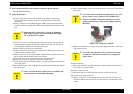
n Make sure to connect PE sensor cable, CR motor
connector cable and Head FFC to the connector (CN5,
CN7, CN8, CN9) on main board.
n Make sure that Shield plate FFC on Head FFC is
securely pasted on [Mounting Plate, M/B].
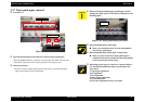
n Make sure that two dowels of Clamp core is set in home
position direction.
n Make sure that PE sensor cable & CR motor connector
cable are set on Holder shaft unit, and in Clamp core.
n Do not touch LD roller.
n Do not damage the tooth of Spur gear 36.8 and
Combination gear 27.2, 19.2.
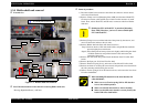
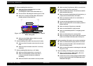
o When assembling Panel board to Holder shaft unit,
(This operation is done after installing Holder shaft unit to
main frame.)
n Make sure to install Panel board correctly.
n Make sure to place Panel board connector cable on the
suitable position of Holder shaft unit.
A D J U S T M E N T
R E Q U I R E D
o When Holder shaft unit is removing or replacing Holder
shaft unit with new one, the following adjustment must be
performed in the order below.
1) Top margin adjustment
2) 1st dot adjustment