


EPSON Stylus C63/64/83/84 Revision A
Disassembly and Assembly Disassembly 28
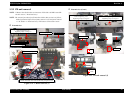
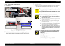
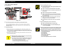
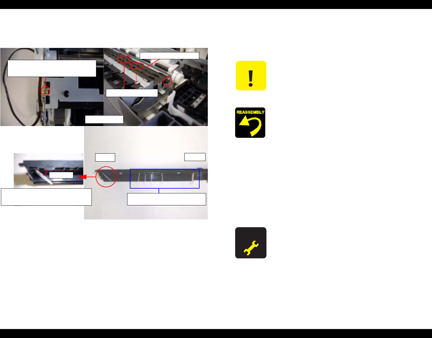
1.3.11 Paper guide front removal
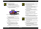
o External view
Figure 1-17. Paper guide front removal
o
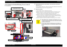
Part/Unit that should be removed before removing Paper guide front
Housing (Right/Left/Frame) / CR unit with Front frame / Paper eject roller
o Removal procedure
1) Remove one screw for securing Paper guide front to main frame, and remove
Paper guide front with pulling the left side of Paper guide front slightly.
Paper guide front
Screw type : CBS TITE SCREW, 3x6, F/Zn
Order of tightening : First
Thghtening torque : 8
±
1 kgf.cm
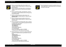
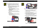
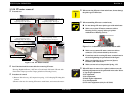
Porous Pad, Paper guide front
Ribs of Paper guide front
HP side
Far side
Angle of two feet is within 45-degrees.
(If angle is over 45-degrees, these feet is set on
the position without [Porous Pad, Ink Eject].)
45-degrees
Remaining feet should be vertically set
be touched to [Porous Pad, Ink Eject]
C A U T I O N
o Do not touch the rib of Paper guide front and [Porous Pad,
Paper guide, Front].
o Do not touch eight feet of [Porous Pad, Paper guide, Front;
Sub].
o When assembling Paper guide front to main frame,
n Do not touch the rib of Paper guide front and [Porous
Pad, Paper guide, Front].
n Make sure to install the dowels of Paper guide front into
the holes of main frame.
n Make sure that there is no gap between Paper guide
front and main frame.
n Be careful not to bend eight feet of [Porous Pad, Paper
guide, Front; Sub] in assembling/disassembling.
n Wipe off drain ink on ribs of Paper guide front by the
cotton stick. (In this time, do not touch the cotton stick
to [Porous Pad, Paper Guide Front] that soluble oid is
included.)
A D J U S T M E N T
R E Q U I R E D
o When Paper guide front is removed or replaced with new
one, the following adjustment must be performed in the
order below.
1) Top margin adjustment
2) PF adjustment
3) Bi-d adjustment
4) Head angular adjustment
5) 1st dot adjustment
6) PW sensor adjustment (Only for SC83/84)