


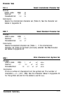

l
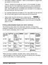
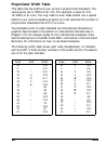
The column heading “Direction” refers to the direction of signal flow
as viewed from the printer.
•
“Return” denotes the twisted-pair return, to be connected at signal
ground level. For the interface wiring, be sure
to
use a twisted-pair
cable for each signal and to complete the connection on the return
side. These cables should be shielded and connected to the chassis of
the host computer and the printer.
l
All interface conditions are based on TTL level. Both the rise and the
fall times of each signal must be less than 0.2 microseconds.
l
Data transfer must be carried out by observing the ACKNLG or
BUSY signal. Data transfer to this printer can be carried out only
after receipt of the ACKNLG signal or when the level of the BUSY
signal is LOW.
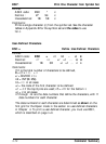
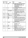
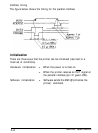
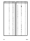
Printing enabled/disabled signals and control conditions
The following table shows the relationship between printing being
enabled or disabled, the on line/off line status, and the receipt of the data
on/off control characters, DC1 or DC3.
*While printing is disabled, character data is being received and
acknowledged so that the printer can look for another DC1 character,
which would allow it to resume printing.
Technical Specifications
A-7