


INSTALLATION LBI-39076
B
19
End-to-End, Loop Start
Ring
Det.
Loop
Current
Det.
Trans-
former
Hybrid
Send
Rec
Ring
Tip
K2
4
5
6
7
8
3
2
1
K3
JP3-B
JP2-B
JP15-A
JP14-A
JP8-A
JP9-B
JP13-A
Audio
Audio
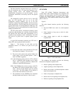
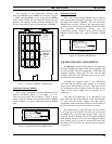
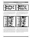
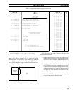
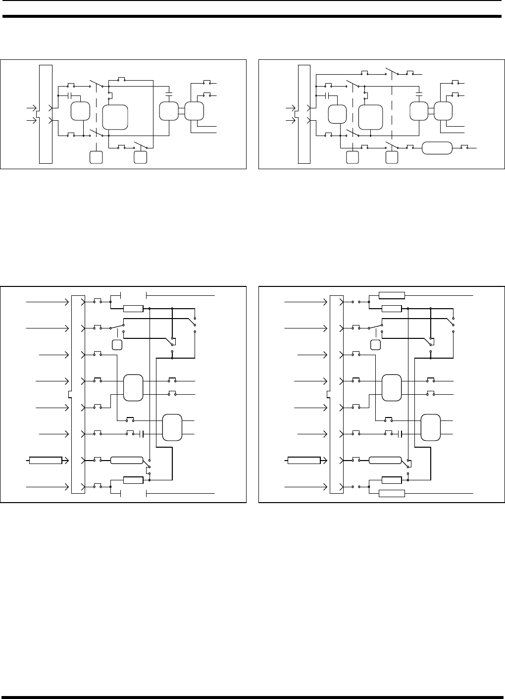
Figure 19 - End-to-End Loop Start (Rev A Main Board)
Figure 19 shows the GTI telephone interface configured
per Table 2 for End-to-End, Loop Start. Two wires are
needed to connect to the telephone company side. Battery
for the loop current is provided by the telephone office.
4-Wire E&M, Microwave
EA
MA
Trans-
former
former
Trans-
E-Lead Det.
4
5
3
6
2
1
7
8
Rec Audio
Send Audio.
4-W Rec
4-W Send
4-W Send
4-W Rec
MB
EB
-48 V
Res
JP4
JP5
JP6-C
JP6-M
GND
Res
K2
JP3-C
JP2-C
JP3-A
JP2-A
JP12-A
JP12-B
JP1-A
JP1-B
JP1-E
JP1-M
JP15-B
JP14-B
IDLE
BUSY
JP10
JP11
1000 Ohms
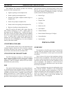
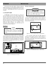
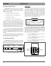
Figure 20 - 4-Wire E&M Microwave (Rev A Main Board)
Figure 20 shows the GTI telephone interface configured
per Table 2 for 4-Wire E&M, Microwave. Eight wires are
needed to connect to the telephone company side, and 1000
ohms must be installed in series with the E-Lead. The
interface interprets the absence of E-Lead current as an idle
condition. The interface provides an opened-loop M-Lead
for an idle condition and a closed-loop for a busy condition.
End-to-End, Ground Start
Ring
Det.
Loop
Current
Det.
Trans-
former
Hybrid
Send
Rec
Ring
Tip
K2
Current Det.
-48V
4
5
6
7
8
3
2
1
K3
GND
JP3-B
JP1-D JP1-M
JP2-B
JP15-A
JP14-A
JP9-A JP8-B JP12-B
JP13-A
Audio
Audio
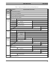
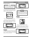
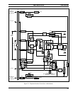
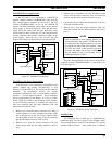
Figure 21 - End-to-End Ground Start (Rev A Main Board)
Figure 21 shows the GTI telephone interface configured
per Table 2 for End-to-End, Ground Start. Two wires are
needed to connect to the telephone company side. Battery
for the loop current is provided by the telephone office.
4-Wire E&M, Type I
EA
MA
Trans-
former
former
Trans-
E-Lead Det.
4
5
3
6
2
1
7
8
Rec Audio
Send Audio.
4-W Rec
4-W Send
4-W Send
4-W Rec
MB
EB
-48 V
Res
JP4
JP5
JP6-C
JP6-M
GND
Res
K2
JP3-C
JP2-C
JP3-A
JP2-A
JP12-A
JP12-B
JP1-A
JP1-B
JP1-E
JP1-M
JP15-B
JP14-B
IDLE
BUSY
JP10
JP11
1000 Ohms
FUSE F3
FUSE F2
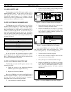
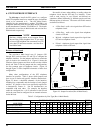
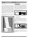
Figure 22 - 4-Wire E&M Type 1 (Rev A Main Board)
Figure 22 shows the GTI telephone interface configured
per Table 2 for 4-Wire E&M, Type I. Six wires are needed
to connect to the telephone company side, and 1000 ohms
must be installed in series with the E-Lead. The interface
interprets the absence of E-Lead current as an idle condition.
The interface provides an open M-Lead for an idle condition
and applies -48 V for a busy condition.