


LBI-39076B FIGURES AND TABLES
6
LIST OF FIGURES AND TABLES (Cont.)
PAGE
Figure 31 - MASTR II & IIe Connections................................................................................................... 25
Figure 32 - PCM / Data Bus Cable.............................................................................................................. 26
Figure 33 - Site Controller Computer Connections ..................................................................................... 26
Figure 34 - IAM Software Locations........................................................................................................... 26
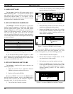
Figure 35 - IAM Software Label.................................................................................................................. 27
Figure 36 - IAM Rear Panel Connections.................................................................................................... 27
Figure 37 - IAM Power Supply Connections............................................................................................... 27
Figure 38 - IAM Alarm Outputs .................................................................................................................. 27
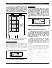
Figure 39 - IAM Printer RS-232 Port .......................................................................................................... 28
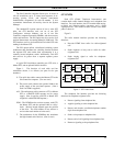
Figure 40 - IAM DIP Switch Settings.......................................................................................................... 28
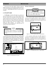
Figure 41 - Local GTI Connection for 9-Pin COM Port.............................................................................. 34
Figure 42 - Local GTI Connection for 25-Pin COM Port............................................................................ 34
Figure 43 - Front Panel of GTI Unit............................................................................................................ 35
Figure 44 - Front Panel of IAM................................................................................................................... 35
Figure 45 - Position of Temporary Jumper.................................................................................................. 43
Table 1 - Sequence of Installation Activities (with Step # References)....................................................... 13
Table 2 - Configurations by Line Type (Rev A Main Board)...................................................................... 18
Table 3 - Configurations by Interface Characteristic (Rev A Main Board) ................................................. 19
Table 4 - Configurations (Rev D or E Main Board) .................................................................................... 22
Table 5 - Defined DIP Switch Settings for GTI Units................................................................................. 23
Table 6 - Local Interconnect Timing Parameter Adjustments For Release 7............................................... 30
Table 7 - Software Compatibility by Release Number ................................................................................ 44
Table 8 - Software Compatibility by Main Board Revision Number........................................................... 45
Table 9 - Troubleshooting Symptoms.......................................................................................................... 51