


MAINTENANCE LBI-39076
B
47
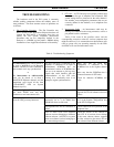
4. Each GTI in 1st Group (Modify 1st Group):
• (MASTR II & IIe applications only) - Add a
jumper between pins 2 and 3 of the Power/Audio
plug on the back panel of the GTI (see Figure 45).
• Disconnect the Power/Audio plug (you will need a
pair of pliers to pull the plug out of the recessed
connector) and Phone plug from the back panel of
the GTI unit.
• Remove the GTI unit from the cabinet, and remove
the top cover.
• If the Main Board is Revision A, replace with a
Revision D or E Main Board.
• Replace the GTI DSP software on the Main Board
with V2.03 GTI DSP software.
• Replace the GTI 552 software on the Main Board
with V2.3 GTI 552 software.
• Replace the GTI Main software on the Processor
Board with V2.14 GTI Main software.
• Re-attach the top cover, and re-install in cabinet
(don’t forget to fasten rear supports).
• Re-connect the Power/Audio plug and Phone plug
to the back panel of the GTI unit (absolutely DO
NOT reconnect the PCM Data Bus at this time).
• (MASTR II & IIe applications only) - Remove the
jumper between pins 2 and 3 of the Power/Audio
plug on the back panel of the GTI (see Figure 45).
• Repeat for each GTI unit in the first group.
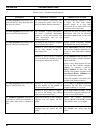
5. System Manager (Disable All):
• Using System Manager screen 10, panel 1:4,
reconfigure the “Interconnect” field to “N” for each
radio channel.
• Using System Manager screen 14, reconfigure the
“Line Active” field to “N” for each line number.
6. Master GTI (Modify Master GTI):
• (MASTR II & IIe applications only) - Add a
jumper between pins 2 and 3 of the Power/Audio
plug on the back panel of the GTI (see Figure 45).
• Disconnect the Power/Audio plug (you will need a
pair of pliers to pull the plug out of the recessed
connector), Phone plug, PCM Data Bus plugs, and
two Site Controller data link plugs from the back
panel of the Master GTI unit.
• Remove the Master GTI unit from the cabinet, and
remove the top cover.
• If the Main Board is Revision A, replace with a
Revision D or E Main Board.
• Replace the GTI DSP software on the Main Board
with V2.03 GTI DSP software.
• Replace the GTI 552 software on the Main Board
with V2.3 GTI 552 software.
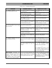
• Temporarily remove the GTI Interface Board from
over the Processor Board.
• Replace the GTI Main software on the Processor
Board with V2.14 GTI Main software.
• Re-install the GTI Interface Board over the
Processor Board.
• Replace the GTI Master software on the GTI
Interface Board with V1.04 GTI Master software.
• Re-attach the top cover, and re-install in cabinet
(don’t forget to fasten rear supports).
• Re-connect the Power/Audio plug, Phone plug,
PCM Data Bus plugs, and two Site Controller data
link plugs to the back panel of the Master GTI unit.
• (MASTR II & IIe applications only) - Remove the
jumper between pins 2 and 3 of the Power/Audio
plug on the back panel of the GTI (see Figure 45).
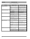
7. Each GTI in 1st Group (Re-connect 1st Group):
• Re-connect the PCM Data Bus plugs to the back
panel of each GTI unit in the first group (must
temporarily disconnect the segments of the bus).
8. Each GTI in 2nd Group (Disconnect 2nd Group):
• Disconnect the PCM Data Bus plugs from the back
panel of each GTI unit in the second group, but re-
connect the segments to maintain bus continuity
end-to-end.