


INSTALLATION LBI-39076
B
23
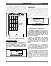
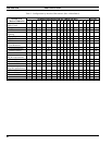
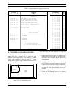
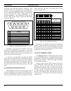
Table 5 - Defined DIP Switch Settings for GTI Units
1 2 3 4 5 6 7 8
DIP SWITCH #
1 0 0 0 0 0 X X
0 1 0 0 0 0 X X
1 1 0 0 0 0 X X
0 0 1 0 0 0 X X
1 0 1 0 0 0 X X
0 1 1 0 0 0 X X
1 1 1 0 0 0 X X
0 0 0 1 0 0 X X
1 0 0 1 0 0 X X
0 1 0 1 0 0 X X
1 1 0 1 0 0 X X
0 0 1 1 0 0 X X
1 0 1 1 0 0 X X
0 1 1 1 0 0 X X
UNIT
GTI
1
2
3
4
5
6
7
8
9
10
11
12
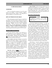
BANK SW1
#1 2 3 4 5 6 7 8
DIP SWITCH #
BANK SW2
1 0 0 X X X X X 2-Wire End-to-End loop start
0 1 0 X X X X X 2-Wire End-to-End ground start
0 0 1 1 X X X X 4-Wire E&M Overdial-PBX
1 1 0 0 X X X X
X X X X X 0 0 0 300 Baud
X X X X X 1 0 0 1200 Baud
X X X X X 0 1 0 2400 Baud
X X X X X 1 1 0 4800 Baud
X X X X X 0 0 1 9600 Baud
X X X X X 1 0 1 19200 Baud
Configurator Terminal
Serial Data Rate:
Line Type:
Telephone
BELOW
PARAMETER
SEE
1 1 1 1 0 0 X X
1 0 0 0 1 0 X X
0 1 0 0 1 0 X X
1 1 0 0 1 0 X X
0 0 1 0 1 0 X X
1 0 1 0 1 0 X X
0 1 1 0 1 0 X X
1 1 1 0 1 0 X X
0 0 0 1 1 0 X X
1 0 0 1 1 0 X X
0 1 0 1 1 0 X X
1 1 0 1 1 0 X X
0 0 1 1 1 0 X X
1 0 1 1 1 0 X X
0 1 1 1 1 0 X X
13
14
15
0 0 0 0 1 0 X X
1 1 1 1 1 0 X X
0 0 0 0 0 1 X X
16
17
18
19
20
21
22
23
24
25
26
27
28
29
30
31
32
0 0 0 X X X X X No Telephone Line Connected
1 0 1 0 X X X X 4-Wire E&M Type 1 Immediate Start
DID Immediate Start
1 1 0 0 X X X X
1 1 0 1 X X X X DID Wink Start
0 = DIP Switch Lever Down
1 = DIP Switch Lever Up
X = DIP Switch Lever Down or Up
1 0 1 1 X X X X 4-Wire E&M Type 1 Wink Start
4-Wire E&M Overdial-Microwave
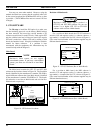
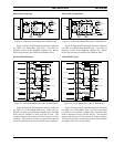
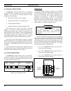
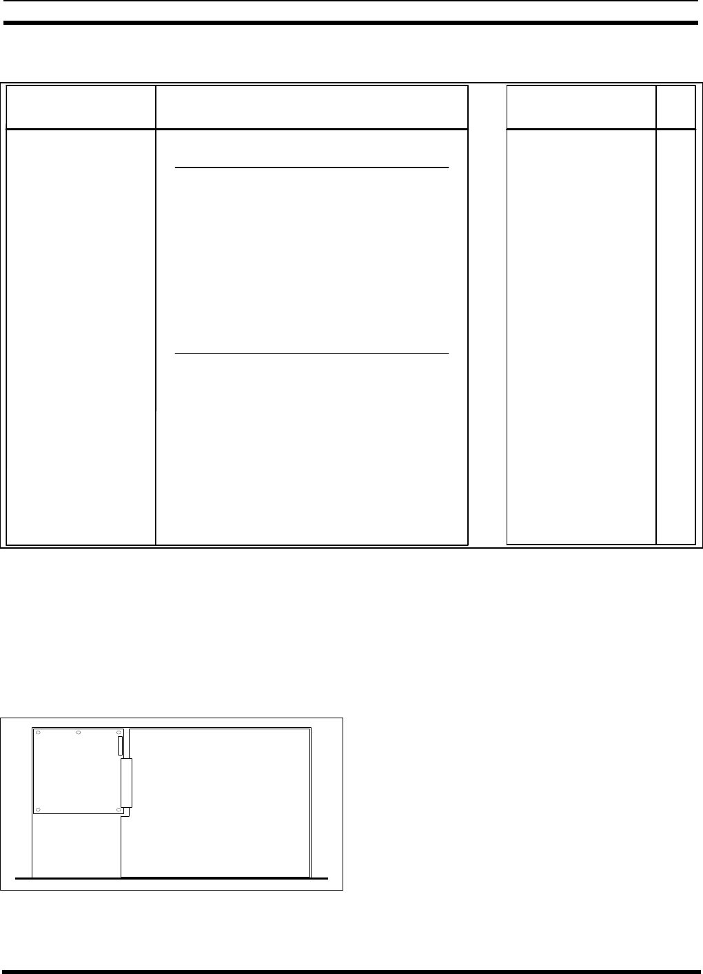
8. GTI INTERFACE BOARD MOUNTING
The
8th step
to install the ELI option, is to make a
Master GTI from a standard GTI by adding the GTI
Interface board. Each standard GTI contains two printed
circuit boards, mounted as shown in Figure 27. A third
board, the GTI Interface board, is added to one GTI unit at a
site, making it the Master GTI.
FRONT
MAIN
BOARD
PROCESSOR
BOARD
P1
Figure 27 - GTI Circuit Board Layout
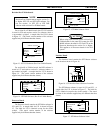
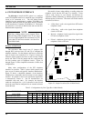
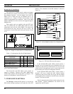
After the cover has been removed, add the GTI
Interface board as follows:
1. Remove the five screws (don't throw them away)
holding the GTI Processor board, and replace them
with five screw-in standoffs supplied with the GTI
Interface board.
2. Carefully position the GTI Interface board above
the GTI Processor board, so that the 14 pins of P1
on the GTI Processor board line up with the 14-pin
socket on the under side of the GTI Interface board,
and push the GTI Interface board down to the
standoffs.
3. Fasten the GTI Interface board to the standoffs
using the five screws removed in step 1.