LBI-39076B INSTALLATION
24
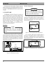
9. GTI & IAM MOUNTING
The
9th step
to install the ELI option, is to mount the
standard GTI units, the Master GTI, and optional IAM (if
supplied). Be sure that the following items have been
completed before mounting:
• Recorded all software version numbers
• Installed GTI interface card in Master GTI
• Set up telephone interface
• Set DIP switches (GTI units and Master GTI)
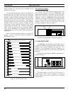
The method used to mount GTI units in repeater
cabinets is to mount all of the standard GTI units first,
followed by the Master GTI. Start by mounting the first
standard GTI just above the GETC for the highest numbered
radio channel, the next GTI just above the GETC for the
next highest numbered radio channel, and so on until all
standard GTI units, and then the Master GTI are mounted.
You may use some other method. However, using the
method described here assures that the supplied cables will
be the correct length and the PCM/Data Bus will be as short
as possible. (The PCM/Data Bus must not exceed 120 feet
in length).
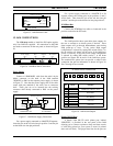
The 350A1154G1 GTI hardware kit, supplied with each
GTI unit, provides a pair of offset brackets to brace the rear
of the GTI unit to the back rails of the cabinet.
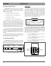
10. GTI CONNECTIONS
The
10th step
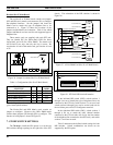
to install the ELI option, is to make the
connections to the GTI units (including the Master GTI).
All of the connections can be made to the connectors on the
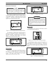
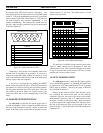
rear panel as shown in Figure 28.
PCM/Data
Line
Telephone GTI Configurator
To Port 30
To Port 31
Master GTI Connections to Site Controller Computer
Repeater Audio
RS-232 Port
Bus
POWER/AUDIOPHONE PCM/DATA BUS
PROGRAM
J3
Power Supply/
(J3)(J2)(P1)(J1)
J4 J5
Figure 28 - Connections to GTI
Telephone Line
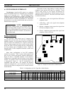
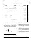
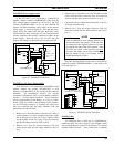
The ELI TELCO Interface module, in the EDACS
Interface panel at the top of each repeater cabinet, is used to
consolidate the telephone connections for 6 telephone lines
from up to 6 GTI units into a single 25-pair IDC telco
connector for connection to a Type 66 (or equivalent)
punchblock and the telephone company. A second 25-pair
IDC telco connector is provided on each module to allow a
25-pair cable to connect this module in tandem with a
similar module in an adjacent repeater cabinet.
All telephone lines must come through
protected punchblocks (or equivalent
protection) before being connected to this
equipment.
CAUTION
For each GTI unit that will be connected to a telephone
line, connect a cable from the female 8-pin modular RJ-45
connector on the back of the GTI unit to one of the female
8-pin modular RJ-45 connectors (J1 through J6) on the front
of the ELI TELCO interface module in the EDACS Interface
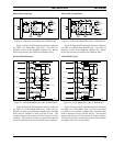
Panel at the top of the cabinet (see Figure 29). Use a cable
that matches the location of the GTI unit:
• Use a 44" 19B803829P1 cable when the GTI is
located with the top repeater.
• Use a 60" 19B803829P2 cable when the GTI is
located with the middle repeater.
• Use a 76" 19B803829P3 cable when the GTI is
located with the bottom repeater.
Company
Telephone
Connections
GTI
Connections
J14 J15
J1
J2
J3
J4
J5
J6
ELI TELCO
Figure 29 - Connections to ELI TELCO Interface Module


