


MAINTENANCE LBI-39076
B
45
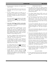
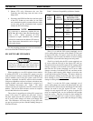
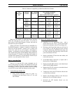
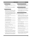
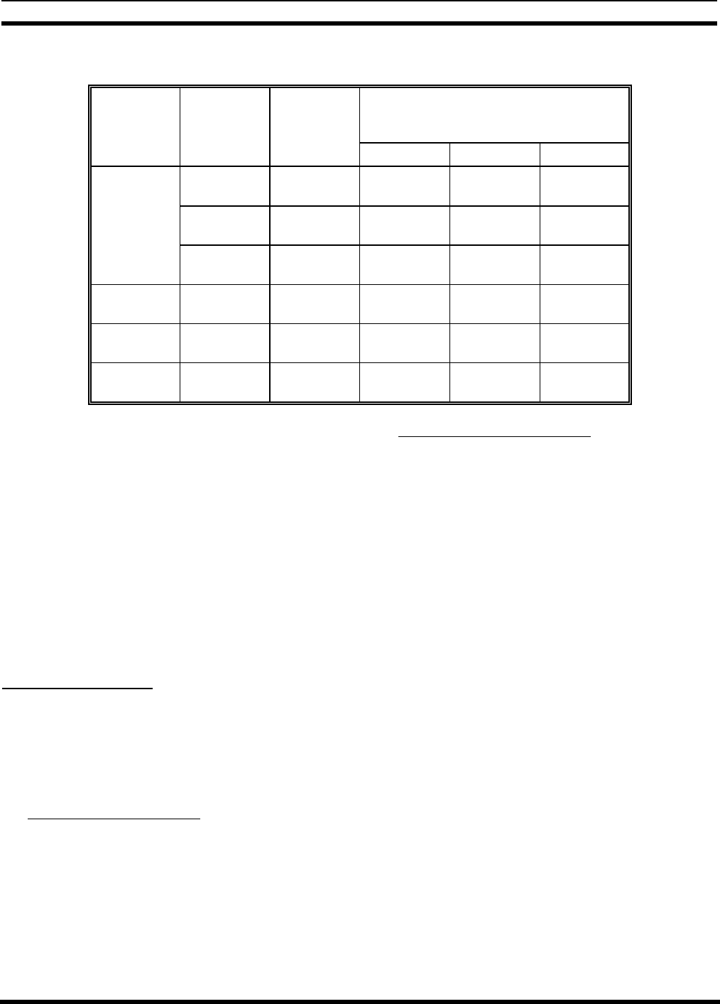
Table 8 - Software Compatibility by Main Board Revision Number
ELI
EQUIPM-
ENT
CIRCUIT
BOARD
SOFTWARE
PACKAGE
SOFTWARE VERSION
REQUIRED FOR
MAIN BOARD REVISION NUMBER
Revision A Revision D Revision E
GTI
Unit
Main
Board
GTI DSP V1.00 V2.01 or
V2.03
V2.01 or
V2.03
Main
Board
GTI 552 V1.3 V2.1 or
V2.3
V2.1 or
V2.3
Processor
Board
GTI Main V1.03 V2.01 or
V2.14
V2.01 or
V2.14
Master GTI
Unit Only
Interface
Board
GTI Master V1.02 V1.02 or
V1.04
V1.02 or
V1.04
IAM GTI IAM V1.2 V1.2 or
V1.30
V1.2 or
V1.30
GTI
Configurator
GTI
Configurator
V1.3 V1.3 or
V2.10
V1.3 or
V2.10
Read over the details of each plan before deciding
which will work best for your ELI system. If you have a
new version of GTI IAM software to install, wait until all
GTI units have been completed.
When a GTI unit is disconnected from a MASTR II or
IIe EDACS Repeater, a jumper is required to maintain the
audio loop for the repeater. Failure to use a jumper will
result in no audio for any call assigned to that repeater’s
channel. An alternative to using the jumper is to disable the
radio channel through the System Manager (RF parameter in
screen 20, panel 1:5). However, this reduces the number of
available radio channels by one and therefore should only be
used for a very short period of time, if at all.
Plan A - All at One Time
Plan A is to take the ELI system completely out of
service while changes are made to the Master GTI unit and
all regular GTI units. This plan is easiest for those making
the changes to the GTI units, but hardest for those wanting
to use the ELI system while the changes are being made.
1. System Manager (Disable All):
• Using System Manager screen 10, panel 1:4,
reconfigure the Interconnect field to N for each
radio channel.
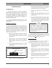
2. Master GTI (Modify Master GTI):
• (MASTR II & IIe applications only) - Add a
jumper between pins 2 and 3 of the Power/Audio
plug on the back panel of the GTI (see Figure 45).
• Disconnect the Power/Audio plug (you will need a
pair of pliers to pull the plug out of the recessed
connector), Phone plug, PCM Data Bus plugs, and
two Site Controller data link plugs from the back
panel of the Master GTI unit.
• Remove the Master GTI unit from the cabinet, and
remove the top cover.
• If the Main Board is Revision A, replace with a
Revision D or E Main Board.
• Replace the GTI DSP software on the Main Board
with V2.03 GTI DSP software.
• Replace the GTI 552 software on the Main Board
with V2.3 GTI 552 software.
• Temporarily remove the GTI Interface Board from
over the Processor Board.
• Replace the GTI Main software on the Processor
Board with V2.14 GTI Main software.
• Re-install the GTI Interface Board over the
Processor Board.