LBI-39076B INSTALLATION
20
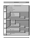
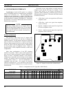
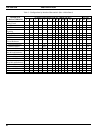
Table 3 - Configurations by Interface Characteristic (Rev A Main Board)
INTERFACE JUMPER POSITIONS FOR JP1 THROUGH JP15 FUSES
CHARACTERISTIC 1 2 3 4 5 6 7 8 9 10 11 12 13 14 15 F2 F3
Audio Circuit
2-Wire B B A A
4-Wire A+C A+C B B
Signaling
Loop Start A B A
Ground Start B A B A
E&M C+M IN IN
E-Lead Reference
External Reference IN A OUT
Internal Ground OUT A IN
Internal -48 V OUT OUT B IN
Idle M-Lead Reference
External Reference A IN not B OUT
Internal Ground B OUT IN
Internal -48 V A OUT IN
Busy M-Lead Reference
External Reference E IN not B OUT
Internal Ground M OUT IN
Internal -48 V E OUT IN


