


INSTALLATION LBI-39076
B
27
2#56022
601-0537
(C) ZETRON INC.
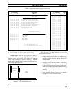
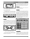
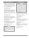
U23
IAM V1.2
Software Version #
Circuit Symbol
Figure 35 - IAM Software Label
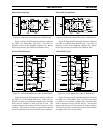
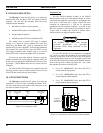
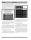
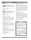
12. IAM CONNECTIONS
The
12th step
needed to install the ELI option applies
only if an IAM was supplied. All connections to the IAM
are made to connectors on the rear panel, as shown in Figure
36.
PCM / Data
Bus
Power Supply
Printer
RS-232 Port
PRINTER
P2
ALARM
Outputs
Alarm
POWER
(P1) (J2) (P2) (J3)
Figure 36 - IAM Rear Panel Connections
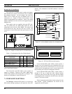
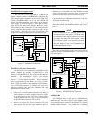
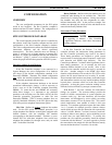
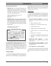
Power Supply
Connect a 19B803968P1 cable from the male 1x6-pin
Molex connector on the back of the IAM (marked
"POWER") to P801 on the repeater power supply, as shown
in Figure 37. Note that the power supply end of the cable
comes with pins attached to the wires, but no connector
shell. These pins are to be inserted into the existing
connector shell already connected to P801 on the power
supply.
IAM Power Supply
3
*
P801
6
5
19B803968P1 Cable
POWER
Gnd
+12 Vdc
Neg
Pos
Existing Connector
Red
Black
* 5 for MASTR II and IIe
6 for MASTR III
Figure 37 - IAM Power Supply Connections
For a power supply connected to a MASTR III repeater,
insert the pin on the red wire into pin position 3 and the pin
on the black wire into pin position 6.
For a power supply connected to a MASTR II or IIe
repeater, remove the existing pins in pin positions 3 and 5,
and tie back. Then insert the pin on the red wire into pin
position 3 and the pin on the black wire into pin position 5.
PCM/Data Bus
Connect the PCM/Data bus cables as instructed in the
previous section for the GTI units.
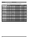
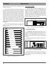
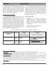
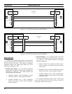
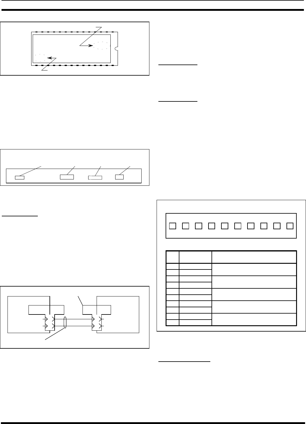
Alarm Outputs
The IAM provides three open-drain alarm outputs for
the user to connect to an alarm system, if desired. These
alarm outputs will go through indeterminate states during
IAM power-up or reset. If the Active High output
configuration is selected by setting DIP switch section 7 to
the up position, all alarms will be active if the IAM loses
power. Conversely, if the Active Low output configuration
is selected by setting DIP switch section 7 to the down
position, no alarms will be active if the IAM loses power.
The standard ELI option does not provide a cable for this
connection, but pin-out information is shown in Figure 38.
Pins 7 through 10 are not used.
12345678910
Pin Alarm Function
1
2
3
4
5
Ground
Ground
Ground
Ground
Ground
Alarm 1
Alarm 2
Alarm 3
Alarm 4
Alarm 5
SMDR Full or Memory Error
6
7
8
9
10
Bus Failure
Low Battery
Not Used
Not Used
ALARM OUTPUTS CONNECTOR
Figure 38 - IAM Alarm Outputs
Printer RS-232 Port
A female 9-pin RS-232 serial printer port, labeled
“PRINTER”, is provided in the rear panel of the IAM
allowing you to connect a printer to keep real-time records
of calls being placed on your system (a record is printed
after each call ends). The proper baud rate for the port can