


LBI-39076B INSTALLATION
22
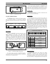
Revision-D or E Main Board
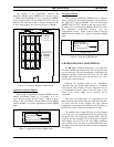
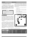
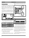
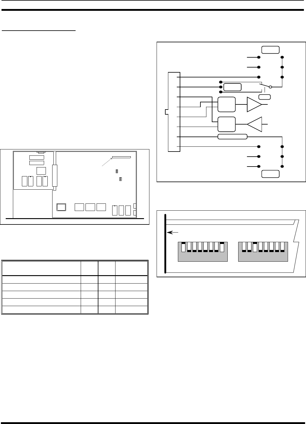
The revision-D or E Main boards contain two jumpers
(JP3 and JP4) and a matrix card connector (J5) to configure
the telephone interface. Set the jumpers and insert the
Matrix card to match the type of telephone line to be
connected to it. Figure 24 shows the locations of the
jumpers and the Matrix card connector. Table 4 lists which
jumpers and Matrix card are used for each supported type of
telephone line.
Three matrix cards are supplied with each GTI unit.
They are labeled E-E (for End-to-End), DID (for direct
inward dial), and 4-W (for 4-Wire E&M). The matrix card
will fit into J5 two ways, but only one way is correct. Be
sure that the A1 end of the matrix card goes into the A1 end
of J5.
FRONT
J5
A1
Matrix Board
A
B
A
B
JP3
JP4
Figure 24 - Jumper Locations (Rev D or E Main Board)
Table 4 - Configurations (Rev D or E Main Board)
TELEPHONE
LINE TYPE
JP3 JP4 MATRIX
CARD
End-to-End, Loop Start B A* E-E
End-to-End, Ground Start B A* E-E
4-Wire E&M, Microwave A A* 4-W
4-Wire E&M, Type I A A* 4-W
DID B A* DID
*Use the B position when the distance to the PBX is short
(gives better hybrid balance).
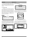
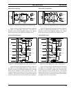
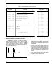
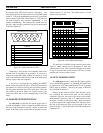
The End-to-End and DID Matrix cards contain no
jumpers to configure. However, the 4-Wire E&M matrix
card has three jumpers (JP1 through JP3) to configure. The
function of each jumper is shown in Figure 25.
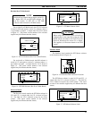
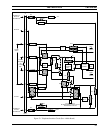
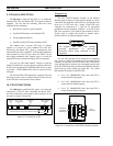
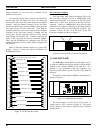
7. GTI DIP SWITCH SETTINGS
The 7th step to install the ELI option, is to set the two
DIP switches through openings in the right side of the GTI
chassis. The orientation of the DIP switches is shown in
Figure 26.
E-Lead
M-Lead
Trans-
former
former
Trans-
E-Lead Det.
4
5
3
6
2
1
7
8
Rec Audio
Send Audio.
4-W Rec
4-W Send
4-W Send
4-W Rec
M-Lead External Reference
E-Lead External Reference
JP3
EXREF
GND
-48
Ground Reference
-48 Vdc Reference
-48 Vdc Reference
Ground Reference
GND
-48
EXREF
JP2
NC
NO
JP1
K2
Figure 25 - 4-Wire E&M Card (Rev D or E Main Board)
18
18
SW2 SW1
FRONT
1
00
1
Figure 26 - GTI Unit DIP Switch Orientation
In the left-hand DIP switch (SW2), switch sections 1
through 4 are set to identify the type of telephone line to be
connected to the GTI unit, switch section 5 is not used, and
switch sections 6 through 8 are used to set the baud rate for
the serial data port to the GTI Configurator terminal.
In the right-hand DIP switch (SW1), switch sections 1
through 6 are set to match the radio channel number
connected to the GTI unit (this will also be the line number
of the telephone line connected to that GTI unit), and switch
sections 7 and 8 are not used.
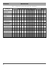
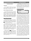
Table 5 summarizes the defined switch settings for both
DIP switches. Switch combinations not shown are not
supported by the ELI option.