


Configuring a Stack
Summit 200 Series Switch Installation and User Guide 239
Enabling a Stack Member
After connecting to the switch through either the console port or through a Telnet session, enter the
following command on each of the stack members:
enable stacking slave ports <portlist>
The ports in the portlist must be Gigabit Ethernet ports (ports 49 and/or 50 on the S200-48 and ports
25 and/or 26 on the S200-24).
After entering the enable stacking slave command, the switch reboots and comes back up using
default information stored in NVRAM. All member switches reboot with an empty configuration. If the
member switch had a previous configuration, it is stored in a small stacking database in NVRAM, so
that it can be restored if you issue the
unconfig stacking command. The saved configuration (either
primary or secondary) is the backup in case the stack fails after the stack is up. All ports are removed
from the default VLAN to prevent broadcast storms.
For information about disabling a stack, see “Changing a Stack Configuration” on page 243.
Stack Discovery
Stack Discovery is a protocol that locates all switches within the stack, then identifies and internally
assigns unique identifiers to all ports in the stack. Stack Discovery begins when any of these conditions
occur:
• The stacking port changes state, either link up or link down
• The enable stacking command executes on a stacking port that is up
• The enable stacking command is issued on a stacking port that is down
• The stack is rebooted with stacking enabled
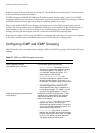
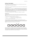
The master assigns the slot numbers for the stack members when the Stack Discovery protocol
converges. If the master is at one end of the configuration, slot 2 becomes the slot closest to the master,
and slot 3 becomes the slot connected to slot 2. The slot assignment continues to the last slot or slot 8.
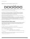
Figure 39: Slot Assignments with the Master at One End of a Chain
If however, the master is in the middle of the chain, then the assignment occurs as if there were two
chains. See Figure 40 for an example of placing a master in the middle of a daisy-chain configuration.
The first chain starts at the stacking port (port 25 on a Summit 200-24 and port 49 on a Summit 200-48).
Slot 2 becomes the switch immediately next to the master, followed by slot 3. When the chain ends, the
slot assignment continues with the switch on the other stacking port.
Slot 4
Port
25/49
Port
26/50
Slot 5 Slot 6Slot 3Slot 2Slot 1
ES2K005