


Creating a Stack
Summit 200 Series Switch Installation and User Guide 31
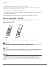
Removing a Mini-GBIC
To remove a mini-GBIC similar to the one labeled “Module A” in Figure 7, gently press and hold the
black plastic tab at the bottom of the connector to release the mini-GBIC, and pull the mini-GBIC out of
the SFP receptacle on the switch.
To remove a mini-GBIC similar to the one labeled “Module B” in Figure 7, rotate the front handle down
and pull the mini-GBIC out of the slot.
Inserting a Mini-GBIC
NOTE
Mini-GBICs can be installed in the SFP mini-GBIC receptacles for ports 25 and 26 on the Summit 200
series switches.
To insert a mini-GBIC connector:
1 Holding the mini-GBIC by its sides, insert the mini-GBIC into the SFP receptacle on the switch.
2 Push the mini-GBIC into the SFP receptacle until you hear an audible click, indicating the mini-GBIC
is securely seated in the SFP receptacle. If the mini-GBIC has a handle, push up on the handle to
secure the mini-GBIC.
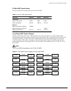
Creating a Stack
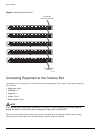
You can physically cable as many as eight Summit 200 switches together to create a virtual chassis
called as stack. You can mix any combination of Summit 200-24 and Summit 200-48 within the stack. The
high-speed one Gigabit Ethernet ports are the backplane of the stack and are called stacking ports. By
creating a stack, users can access and manage the devices using a single IP address.
The stacking configuration retains a high speed port on the end switches as uplinks to the network.
However, these uplink ports may not be configured to be in a load share group. Load sharing is only
supported for ports on the same switch. An example of a stacking configuration is shown in Figure 8.