


30 Summit 200 Series Switch Installation and User Guide
Switch Installation
• Make sure the bend radius of the fiber is not less than 2 inches.
In addition to the previously described tasks, Extreme Networks recommends the following when
installing or replacing mini-GBICs on an active network:
• Use the same type of mini-GBIC at each end of the link.
• Connect one end of the link to the Tx port. Without an attenuator, measure the total loss from the Tx
port to the other side of the link.
Once you complete all of the described tasks, you are ready to install or replace a mini-GBIC.
Removing and Inserting a Mini-GBIC
You can remove mini-GBICs from, or insert mini-GBICs into your Summit 200 series switch without
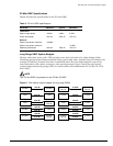
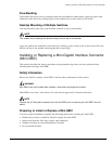
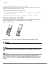
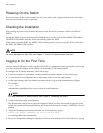
powering off the system. Figure 7 shows the two types of mini-GBIC modules.
Figure 7: Mini-GBIC modules
Mini-GBICs are a 3.3 V Class 1 laser device. Use only devices approved by Extreme Networks.
WARNING!
Mini-GBICs can emit invisible laser radiation. Avoid direct eye exposure to beam.
NOTE
Remove the LC fiber-optic connector from the mini-GBIC prior to removing the mini-GBIC from the
switch.
NOTE
If you see an amber blinking Mini-GBIC port status LED on your Summit 200 series switch, the
mini-GBIC installed in your switch is one that is not approved or supported by Extreme Networks. To
correct this problem, ensure that you install a mini-GBIC that is approved and supported by Extreme
Networks.
XM_02
4
Module A Module B