


Connecting Equipment to the Console Port
Summit 200 Series Switch Installation and User Guide 33
Appropriate cables are available from your local supplier. To make your own cables, pinouts for a DB-9
male console connector are described in Table 10.
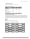
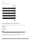
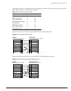
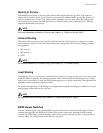
Figure 9 shows the pin-outs for a 9-pin to RS-232 25-pin null-modem cable.
Figure 9: Null-modem cable pin-outs
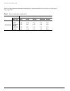
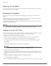
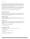
Figure 10 shows the pin-outs for a 9-pin to 9-pin PC-AT null-modem serial cable.
Figure 10: PC-AT serial null-modem cable pin-outs
Table 10: Console Connector Pinouts
Function Pin Number Direction
DCD (data carrier detect) 1 In
RXD (receive data) 2 In
TXD (transmit data) 3 Out
DTR (data terminal ready) 4 Out
GND (ground) 5 —
DSR (data set ready) 6 In
RTS (request to send) 7 Out
CTS (clear to send 8 In
Screen
TxD
RxD
Ground
RTS
CTS
DSR
DCD
DTR
C
able connector: 9-pin female
S
ummit
Cable connector: 25-pin male/fema
le
PC/Terminal
Screen
RxD
TxD
Ground
RTS
DTR
CTS
DSR
DCD
Shell
3
2
5
7
8
6
1
4
1
3
2
7
4
20
5
6
8
ser_sum
1
Screen
DTR
TxD
RxD
CTS
Ground
DSR
RTS
DCD
C
able connector: 9-pin female
S
ummit
Cable connector: 9-pin fema
le
PC-AT Serial Port
Screen
DCD
RxD
TxD
DTR
Ground
DSR
RTS
CTS
Shell
4
3
2
8
5
6
7
1
Shell
1
2
3
4
5
6
7
8
ser_sum
2