


2-3
MVX VGA A Matrix Switchers • Installation
PRELIMINARY
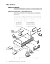
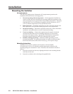
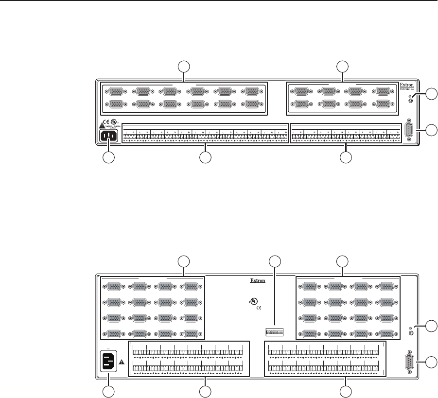
Rear Panel Cabling and Views
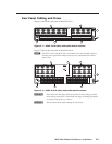
Figure 2-1 shows the rear panel of the MVX 128 A.
RS232/RS422
REMOTE
LIS TED
1T2 3
I.T. E.
1 2 3 4 5 6 7 8
9 10 11 12
1 2 3 4 5 6 7 8
1
2
3
4
5
6
7
8
9
10
11
12
1
2
3
4
5
6
7
8
INPUTS
OUTPUTS
RESET
COMPUTER IN
COMPUTER OUT
8
6
1 2
54
REMOTE
7
Figure 2-1 — MVX 128 A video and audio matrix switcher
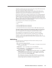
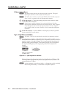
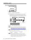
Figure 2-2 shows the rear panel of the MVX 1616 A.
N
The MVX 1212 A and MVX 168 A are housed in the same 3U high enclosure,
but have fewer input and/or output connectors to accommodate their smaller
matrix sizes.
RS-232/RS422
REMOTE
RESET
COMPUTER IN
1
2
5
6
9
10
13
14
3
4
7
8
11
12
15
16
COMPUTER OUT
1
2
5
6
9
10
13
14
3
4
7
8
11
12
15
16
1.2A MAX.
100-240V 50/60 Hz
O
U
T
P
U
T
S
I
N
P
U
T
S
L
15
RL
13
RL
11
RL
9
RL
7
RL
5
RL
3
RL
1
R
L
16
RL
14
RL
12
RL
10
RL
8
RL
6
RL
4
RL
2
R
L
15
RL
13
RL
11
RL
9
RL
7
RL
5
RL
3
RL
1
R
L
16
RL
14
RL
12
RL
10
RL
8
RL
6
RL
4
RL
2
R
12 3 4 56 7 8
12345
50
75
OUTPUT
SYNC IMPEDANCE
678
A na he im,C A
US
LISTE D
1T23
I.T.E.
®
8
7
3
6
1 2
54
COMPUTER IN COMPUTER OUT
OUTPUT
Figure 2-2 — MVX 1616 A video and audio matrix switcher
C
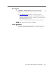
Use Electrostatic discharge (ESD) precautions (be electrically grounded)
when making connections. Electrostatic discharge can damage equipment,
even if you cannot feel, see, or hear it.
C
Remove system power before making all connections.