


4-11
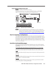
MVX VGA A Matrix Switchers • Programmer’s Guide
PRELIMINARY
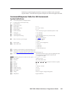
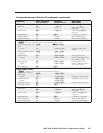
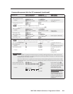
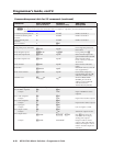
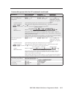
Command/response table for SIS commands (continued)
Command ASCII command
(host to switcher)
Response
(switcher to host)
Additional
description
View ties, gain, volume, mutes, and presets (continued)
View video global preset
configuration
EX(
*1*1VC
} X@
1
•
X@
2
•
...
•
X@
16
•
Vid
]
Show preset
X(
’s video
configuration. Show the
input tied to 16 sequential
outputs.
Command description:
Response description:
preset #*starting output # (O# - should always be 1)*1(=video)VC
input # (I#) tied to O#1
•
I# tied to O#2•I# tied to O#3
•
...
•
I# tied to O#16•Vid
]
N
EX(
*1*1VC
}
where
X(
= 0 returns the switcher’s current video configuration.
Example:
MVX 128 VGA A
1Output:
Response = tied input:
input 12 tied to output 3
2 3 4 5 6 7 8
08•08•12•08•08•11•00•00
no tied input
input 8 tied to output 4
•--•--•--•--•--•--•--•--•
13 14 15 1609 10 11 12
outputs do not exist
•Vid
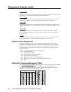
Each position shown in the response is an output: left = output 1, right = output 16.
(Outputs 9 through 16 are not present on the MVX 128 A.) The number in each position
is the input tied to that output.
In this example, video input 8 is tied to outputs 1, 2, 4, and 5; input 12 is tied to output 3;
and input 11 is tied to output 6. No inputs are tied to outputs 7 and 8.
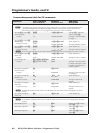
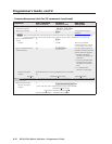
View audio global preset
configuration
EX(
*1*2VC
} X@
1
•
X@
2
•
...
•
X@
16
•
Aud
]
Show preset
X(
’s audio
configuration. Show the
input tied to 16 sequential
outputs.
Command description:
Response description:
preset #*starting output # (O# - should always be 1)*2(=audio)VC
input # (I#) tied to O#1
•
I# tied to O#2
•
I# tied to O#3
•
...
•
I# tied to O#16•Aud
]
N
EX(
*1*2VC
}
where
X(
= 0 returns the switcher’s current audio configuration.
Example:
(MVX 1212 VGA A)
01 Output:
Response = tied input:
input 1 tied to output 3
02 03 04 05 06 07 08
01•01•01•01•02•12•12•00•00•00•00•00•--•--•--•--•Aud
09 10 11 12 13 14 15 16
no tied input outputs do not exist
Each position shown in the response is an output: left = output 1, right = output 16.
(Outputs 13 through 16 are not present on the MVX 1212 A.) The number in each
position is the input tied to that output.
In this example, audio input 1 is tied to outputs 1, 2, 3, and 4; input 2 is tied to output 5;
and input 12 is tied to outputs 6 and 7. No input is tied to outputs 8, 9, 10, 11, and 12.
Serial port configuration
Set serial port parameters
EX1$
*
X1%
,
X1^
,
X1&
,
X1*
CP
}
Cpn
X1$
•Ccp
X1%
,
X1^
,
X1&
,
X1*]
Read port parameters
E
1CP
} X1%
,
X1^
,
X1&
,
X1*]
Set mode
E
1*
X1(
CY
}
Cpn1•Cty
X1(]
Read mode
E
1CY
} X1(]