


3-7
MVX VGA A Matrix Switchers • Operation
PRELIMINARY
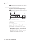
Front Panel Operations
The following paragraphs detail the power-up process and then provide sample
procedures for the following actions:
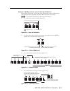
• Creating ties, sets of ties, and configurations
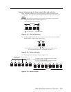
• Changing a configuration
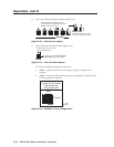
• Viewing ties, sets of ties, and configurations
• Muting and unmuting outputs
• Saving a preset
• Recalling a preset
• Viewing and adjusting the output volume
• Viewing and adjusting the input audio level
• Locking the front panel
• Performing resets from the front panel
• Reading and setting the RS-232/RS-422 Remote port settings
Front panel security lockouts
In the procedural descriptions that follow, it is assumed that the switcher is in Lock
mode 0 (fully unlocked). The following two Lock modes are also available:
• Lock mode 1 — All changes are locked from the front panel (except for setting
Lock mode 2). Some functions can be viewed.
• Lock mode 2 — Advanced features are locked and can be viewed only. Basic
functions are unlocked.
N
The switcher is shipped from the factory in Lock mode 2.
See “Setting the front panel locks (Executive modes)” on page 3-36 for a detailed list
of basic and advanced functions and the procedure to set the various front panel
locks.
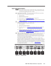
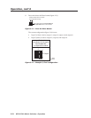
Power
Apply power by connecting the power cord to an AC source. When AC power is
applied, the switcher performs a self-test that flashes the front panel LEDs and then
turns them off. An error-free power up self-test sequence leaves the RGBHV LED
and the Audio LED on, and all other LEDs unlit.
The current configuration and all presets are saved in non-volatile memory. When
power is applied, the most recent configuration is retrieved. The previous presets
remain intact.
If an error occurs during the self-test, the switcher locks up and does not operate.
If your switcher locks up on power-up, call the Extron S
3
Sales & Technical Support
Hotline.