


MVX VGA A Matrix Switchers • Operation
3-2
Operation
PRELIMINARY
N
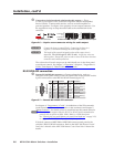
On some MVX switchers, the video selection button is labeled “Video” rather
than “RGBHV”.
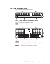
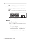
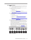
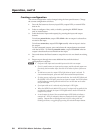
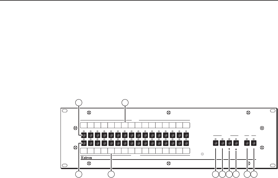
Front Panel Controls and Indicators
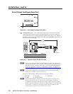
The front panel controls (figure 3-1) are grouped into two sets. The input and
output buttons are grouped on the left side of the control panel. The control
buttons and video/audio (I/O) selection buttons are grouped on the right side of
the panel.
N
The MVX 128 A has a similar front panel configuration, but with fewer input
buttons and output buttons.
MVX SERIES
VGA MATRIX SWITCHER WITH ADPS™
ENTER PRESET VIEW ESC VIDEO AUDIO
CONTROL I/O
OUTPUTS
INPUTS
CONFIG
1 2 3 4 5 6 7 8
1 2 3 4 5 6 7 8
9 10 11 12 13 14 15
9 10 11 12 13 14 15 16
16
6 7 8 93
1 3
2 4 5
Figure 3-1 — Front panel, MVX 1616 A
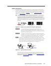
Definitions
The following terms, which apply to all Extron matrix switchers, are used
throughout this manual:
Tie — An input-to-output connection
Set of ties — An input tied to two or more outputs. (An output can never be tied
to more than one input.)
Configuration — One or more ties or one or more sets of ties
Current configuration — The configuration that is currently active in the
switcher (also called “configuration 0”)
Global memory preset — A configuration that has been stored. Up to 32 global
memory presets can be stored in memory. Preset locations are assigned
to the input buttons and output buttons. When a preset is retrieved from
memory, it becomes the current configuration.
The switchers have 32 presets. On the MVX 128 VGA A, up to 20 presets
can be selected from the front panel for either saving or retrieving. Preset
numbers larger than 20 are accessible via serial port control.