


3-21
MVX VGA A Matrix Switchers • Operation
PRELIMINARY
Using global presets
The current configuration (configuration 0) can be saved as a preset in any one of
32 preset memory addresses. Preset locations are assigned to the input buttons
and output buttons. On the MVX 128 A, up to 20 presets can be selected from the
front panel to be either saved or retrieved. On all other models, all 32 presets are
available from the front panel. When a preset is retrieved from memory, it becomes
the current configuration.
N
• Only the audio and video ties are stored and recalled; audio gain settings are
not saved, and they do not change when a preset is recalled.
• Presets cannot be viewed from the front panel unless recalled as the current
configuration. Presets can be viewed using Extron’s Windows-based control
program. See chapter 5, “Matrix Software”, for more details.
• The current configuration and all presets are stored in non-volatile memory.
When power is removed and restored, the current configuration is still active
and all presets are retained.
• When a preset is recalled, it replaces the current configuration, which is lost
unless it is also stored as a preset. The recalled preset overwrites all of the
current configuration ties in favor of the preset configuration ties.
• Preset numbers greater than 20 (that are too high to be available from the
front panel) are accessible via serial port control.
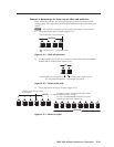
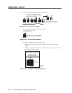
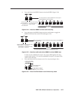
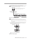
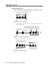
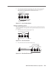
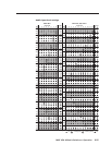
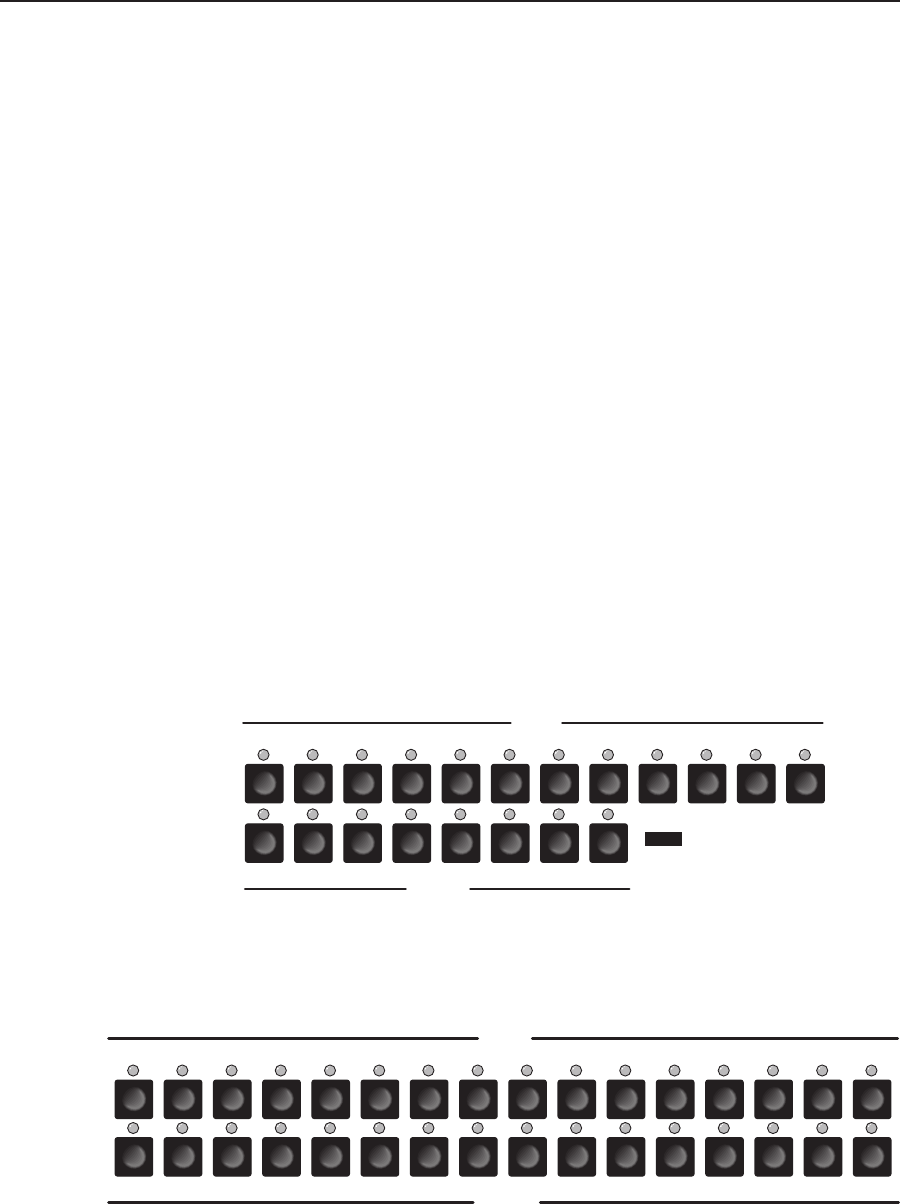
• Figure 3-32 shows the presets associated with the various input and output
buttons for the MVX 128 VGA A. Figure 3-33 shows the presets associated
with the various input and output buttons for the MVX 1212 VGA A,
MVX 168 VGA A, and MVX 1616 VGA A.
Preset
1
Preset
5
Preset
10
Preset
2
Preset
11
Preset
3
Preset
8
Preset
12
Preset
6
Preset
7
Preset
4
Preset
13
Preset
17
Preset
14
Preset
15
Preset
20
Preset
18
Preset
19
Preset
16
NOTE Presets 21 through 32 are
available via serial port
control only.
Preset
9
INPUTS
OUTPUTS
1 2 3 4 5 6 7 8
1 2 3 4 5 6 7 8 9 10 11 12
Figure 3-32 — Preset locations, MVX 128 VGA A
Preset
1
Preset
5
Preset
10
Preset
2
Preset
11
Preset
3
Preset
8
Preset
12
Preset
6
Preset
7
Preset
4
Preset
9
Preset
17
Preset
21
Preset
18
Preset
19
Preset
24
Preset
22
Preset
23
Preset
20
1 2 3 4 5 6 7 8
1 2 3 4 5 6 7 8
9 10 11 12
Preset
13
Preset
25
Preset
14
Preset
26
Preset
15
Preset
27
Preset
16
Preset
28
13 14 15
9 10 11 12
Preset
29
Preset
30
Preset
31
Preset
32
13 14 15 16
16
OUTPUTS
INPUTS
Figure 3-33 — Preset locations, MVX 1212 VGA A, MVX 168 VGA A,
MVX 1616 VGA A