


4-5
MVX VGA A Matrix Switchers • Programmer’s Guide
PRELIMINARY
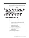
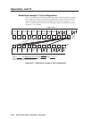
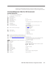
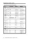
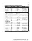
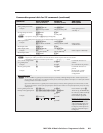
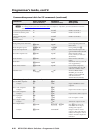
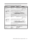
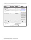
Symbols are used throughout the table to represent variables in the command/
response fields. Command and response examples are shown throughout the table.
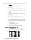
Command/Response Table for SIS Commands
Symbol definitions
]
= CR/LF (carriage return/line feed) (hex 0D 0A)
}
= Carriage return (no line feed, hex 0D))
•
= Space character
E
= Escape key (hex 1B)
X!
= Input number 01 – 16
X@
= Input number (for tie)
00 – 16 (00 = untied)
X#
= Output number 01 – 16
X$
= Numeric dB value –18 to +24 (45 steps of gain or attenuation) (fefault = 0 dB)
X%
= Audio gain 0 – 24 (1 dB/step)
X^
= Audio attenuation 1 – 18 (1 dB/step)
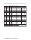
X&
= Volume adjustment range 0 – 64 (1 dB/step except for 0-to-1, which is 13 dB)
(default = 64 [0dB])
(See the table on page 4-8.)
X*
= Mute, Lock mode, or power supply 0 = off/mode 0/not OK
1 = on/mode 1/OK
2 = mode 2
X(
= Global preset # 0 - 32 (0 = current configuration)
X1)
= Video/audio mute 0 = no mute
1 = video mute
2 = audio mute
3 = video and audio mute
X1!
= Firmware version number to second decimal place (x.xx)
X1@
= Verbose firmware version-description-upload date/time.
See the Query controller firmware version (verbose) command on page 4-12.
X1#
= Name 12 characters maximum for input, output, and global preset names
Upper- and lower-case alphanumeric characters and
_ / and spaces are valid.
N
The following characters are invalid in the name: {space} ~ , @ = ‘ [ ] { } < > ’ “ ; : | \ and ?.
X1$
= Port number 1 (front) or 2 (rear)
X1%
= Baud rate 9600, 19200, 38400, 115200
X1^
= Parity Odd, even, none, mark, space (Only the first letter is required.)
X1&
= Data bits 7, 8
X1*
= Stop bits 1, 2
X1(
= Port type 0 = RS-232, 1 = RS-422
X2)
= Number of inputs 12 or 16
X2!
= Number of outputs 8, 12, or 16
X2@
= Part number 68-nnn-nn
X2#
= Voltage Positive or negative voltage and magnitude
X2$
= Temperature Degrees Fahrenheit