


Operation, cont’d
MVX VGA A Matrix Switchers • Operation
3-14
PRELIMINARY
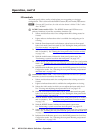
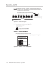
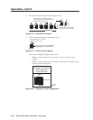
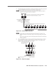
4. Press and release the Output 4 button (figure 3-18).
ENTER PRESE
1 2 3 4 5
OUTPUTS
6
Press and release the Output 4 button.
The LED blinks to indicate that the selected
RGBHV output will be untied.
The Enter LED blinks to indicate
the need to confirm the change.
Figure 3-18 — Deselect the output
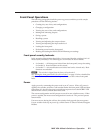
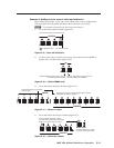
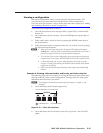
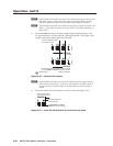
5. Press and release the Enter button (figure 3-19).
ENTER
The Enter LED and all input LEDs and
output LEDs return to the unlit state.
Press the Enter button to confirm
the configuration change.
Figure 3-19 — Press the Enter button
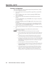
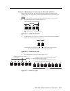
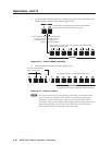
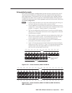
The current configuration (figure 3-20) is now:
• Video — Input 5 (video) is tied to output 1, output 3, output 4, and
output 8.
• Audio — Input 5 (audio) is tied to output 3 and output 8. (Input 5 audio
is no longer tied to output 4.)
Input 5 video tied
to outputs 1, 3, 4, and 8
Input 5 audio tied
to outputs 3 and 8
Input
Output
1
3
4
8
5
Video
Audio
Figure 3-20 — Example 3, final configuration