


3-29
MVX VGA A Matrix Switchers • Operation
PRELIMINARY
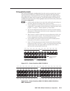
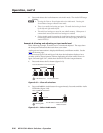
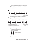
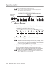
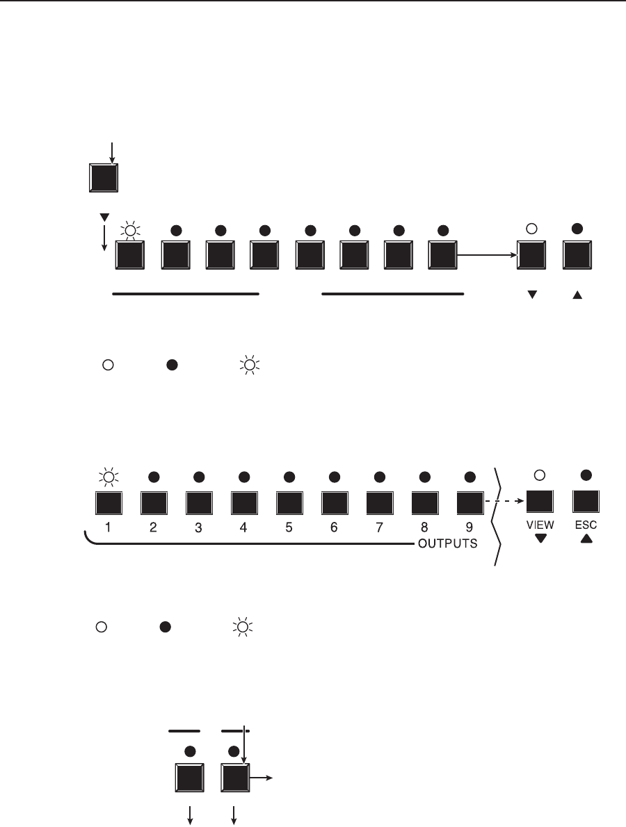
Figure 3-47 shows the result of pressing the View (
<
) button a total of nine
times. Note that the level is now displayed in red to indicate a negative level.
N
Figure 3-47 shows the adjusted level (–1 dB) displayed on the MVX 128 A, an
8-ouput-LED switcher.
1 2 3 4 5
OUTPUTS
6
7 8
VIEW ESC
VIEW
In this example, the output buttons and the View and Esc buttons display an audio gain level of –1 dB.
= Lit LED, = Slow blinking LED= Unlit LED,
The output LEDs display the selected input's audio level. The View and Esc LEDs display
the polarity (gain or attenuation).
Press the View button to decrease the
input audio level by 1 dB per button push.
S
S
Figure 3-47 — Adjust the input audio level
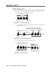
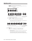
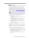
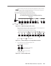
Figure 3-48 shows the same level (–1 dB) as in figure 3-47, but displayed on a
16-ouput-LED switcher, such as an MVX 1616 A.
In this example, the output buttons and the View and Esc buttons
display an audio gain level of –1 dB.
The output LEDs display the selected input's audio level. The View and Esc LEDs
display the polarity (gain
or attenuation).
= Lit LED, = Unlit LED, = Slow blinking LED
S
S
Figure 3-48 — Level display on a 16-output-LED switcher
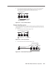
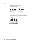
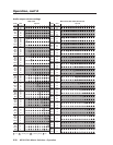
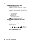
5. Press and release the Audio button (figure 3-49).
RGBHV AUDIO
I/O
The Audio LED stops blinking and lights steadily.
The RGBHV button lights.
Press the Audio button to exit Audio mode.
All input LEDs and output LEDs
return to the unlit state.
Figure 3-49 — Deselect Audio mode