


Operation, cont’d
MVX VGA A Matrix Switchers • Operation
3-34
PRELIMINARY
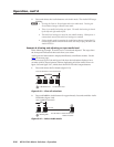
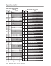
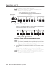
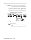
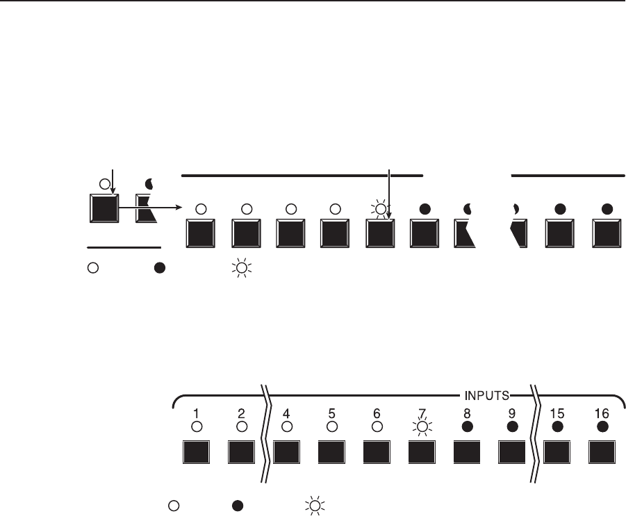
3. Press and release the Output 1 button (figure 3-52).
N
Figure 3-52 shows the volume level (39 dB attenuation) displayed on the
MVX 128 A, an 8-output-LED switcher.
1 2
1 2 3 4 5 6
INPUTS
7 10 11 12
Press and release
the Output 1 button.
The LED lights.
The input LEDs display the selected output's audio volume level.
In this example, the lit input buttons indicate 40 to 41.5 percent of the applied audio
input. The unlit input buttons indicate an audio volume attenuation of 39 dB to 40 dB.
39 dB attenuation,
41.5% volume
= Lit LED, = Slow blinking LED
S
S
= Unlit LED,
Figure 3-52 — Select output 1
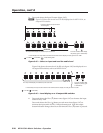
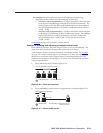
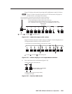
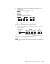
Figure 3-53 shows the same volume (41.5%) as in figure 3-52, but displayed on
a 16-output-button switcher, such as an MVX 168 A.
In this example, the input buttons display an audio gain level of –39 dB.
= Lit LED, = Unlit LED, = Slow blinking LED
S
S
Figure 3-53 — Volume display on a 16-output-button switcher
N
The volume level is protected when front panel Lock mode 2 is selected. You can
view the volume in Lock mode 2 but you cannot change it from the front panel.
If you try to perform step 4 while front panel Lock mode 2 is selected, the actions
are ignored and the Enter, RGBHV, and Audio LEDs flash.
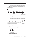
4
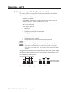
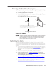
. Press and release the Esc (
>
) button once (figure 3-54) to increase the volume
by 1.5%.
Press and release the Esc (
>
) button several more times (figure 3-54) to
increase the volume by 1.5% per button push. Note the input LED indication
changes that occur each time the Esc (
>
) button is pressed and released.
N
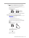
You can press and hold the Esc (
>
) or View (
<
) button to ramp the level up or
down by 3 dB per second to the high or low limit.