


Installation, cont’d
MVX VGA A Matrix Switchers • Installation
2-4
PRELIMINARY
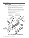
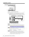
Video connections
N
The matrix switcher does not alter the video signal in any way. The signal
output by the switcher is in the same format as the input.
N
The MVX matrix switchers can also switch RGBS, RGsB, RsGsBs, component
video, S-video, or composite video with the appropriate adapters.
a
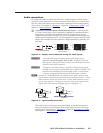
RGB video inputs — Connect the analog computer-video sources to these
15-pin HD female connectors.
N
Most laptop or notebook computers have an external video port, but they
require special commands to output the video to that connector. Also, a laptop’s
screen shuts off once the external video port is activated. See the computer’s
user’s guide for details, or contact Extron for a list of common laptop keyboard
commands.
b
RGB video outputs — Connect RGBHV video displays to these 15-pin HD
female connectors for each output.
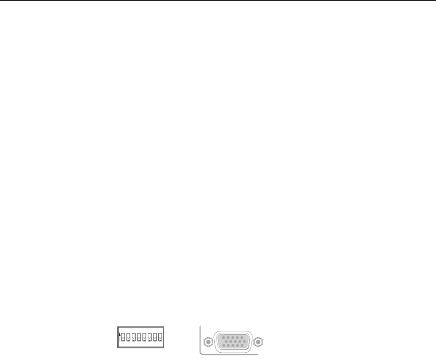
Sync Impedance switches
N
The MVX VGA 128 A does not have the described Sync Impedance switches.
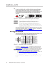
c
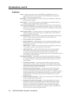
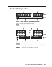
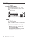
Sync Impedance switches — The MVX 1212 VGA A, MVX 168 VGA A, and
MVX 1616 VGA A matrix switchers have Sync Impedance switches on the rear
panel for outputs 1 through 8 (figure 2-3) to compensate the impendance for
different cable types and lengths. The switches provide a way to condition
the output, enabling the sync to be properly passed from output to the
display.
MVX 1212 A, MVX 168 A
and MVX 1616 A
4
1 2 3 4 5 6 7 8
1 2 3 4 5
50
75
OUTPUT
SYNC IMPEDANCE
6 7 8
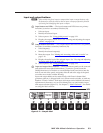
Figure 2-3 — Sync Impedance switches
Each switch provides the option of selecting either 50 ohms or 75 ohms. The
50 ohms position is required only when a sync problem is encountered. The
normal position is 75 ohms.
N
An input producing an out-of-sync display — a display that is rolling vertically
and/or tearing horizontally — could indicate an impedance problem.