


Operation, cont’d
MVX VGA A Matrix Switchers • Operation
3-28
PRELIMINARY
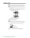
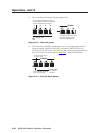
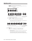
3. Press and release the Input 5 button (figure 3-45).
N
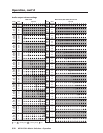
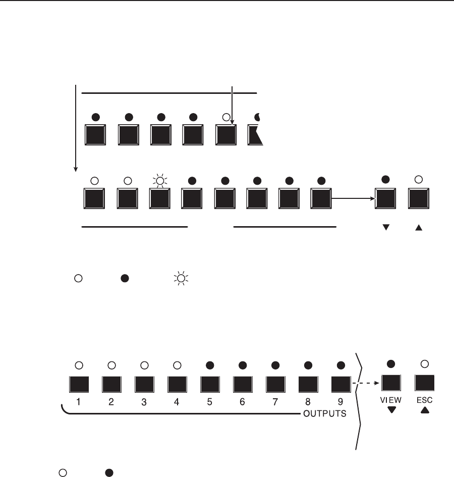
Figure 3-45 shows the current level (+8 dB) displayed on the MVX 128 A, an
8-ouput-LED switcher.
1 2 3 4 5 6
1 2 3 4 5
OUTPUTS
6
7 8
VIEW ESC
Press and release the Input 5 button.
The LED lights.
In this example, the output buttons and the View and Esc buttons display an audio gain level of +8 dB.
= Lit LED,
F
F
= Fast blinking LED= Unlit LED,
The output LEDs display the selected input's audio level. The View and Esc LEDs display
the polarity (gain or attenuation).
Figure 3-45 — Select an input and read the audio level
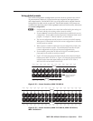
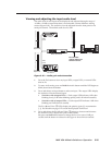
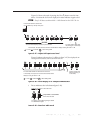
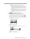
Figure 3-46 shows the same level (+8 dB) as in figure 3-45, but displayed on a
16-ouput-LED switcher, such as an MVX 1212 A.
In this example, the output buttons and the View and Esc buttons display an audio gain level of +8 dB.
= Lit LED, = Unlit LED,
The output LEDs display the selected input's audio level.
The View and Esc LEDs
display the polarity (gain
or attenuation).
Figure 3-46 — Level display on a 16-output-LED switcher
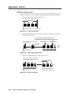
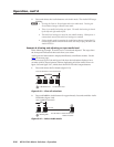
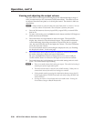
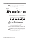
4. Press and release the View (
<
) button once (figure 3-47) to decrease the input
audio level by 1 dB.
Press and release the View (
<
) button several more times (figure 3-47) to
decrease the input audio level by 1 dB per button push. Note the output
button indication changes that occur each time the View (
<
) button is pressed.