


XTP T UWP 302 • Installation and Operation 6
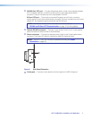
Installing a UL-certified Junction Box
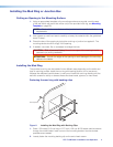
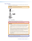
1. Insert the junction box into the hole in the wall.
2. Secure it to the stud using two screws or nails, as appropriate. The front edge of the
junction box must be flush with the front surface of the wall.
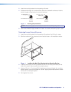
3. Secure cables with clamps or ties to provide strain relief.
4. Trim back and insulate shields with heat shrink.
ATTENTION: To prevent short circuits, the outer foil shield can be cut back to the
point where the cable exits the cable clamp. Both braided and foil shields should
be connected to an equipment ground at the other end of the cable.
Rear and Side Panel Connectors
POWER
12V
0.7A MAX
Tx Rx
G
REMOTE
RS-232
XTP OUT
SIG LINK
Tx Rx
G
OVER XTP
RS-232 IR
Tx
Rx
b
cd
a
Front
Side
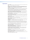
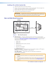
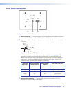
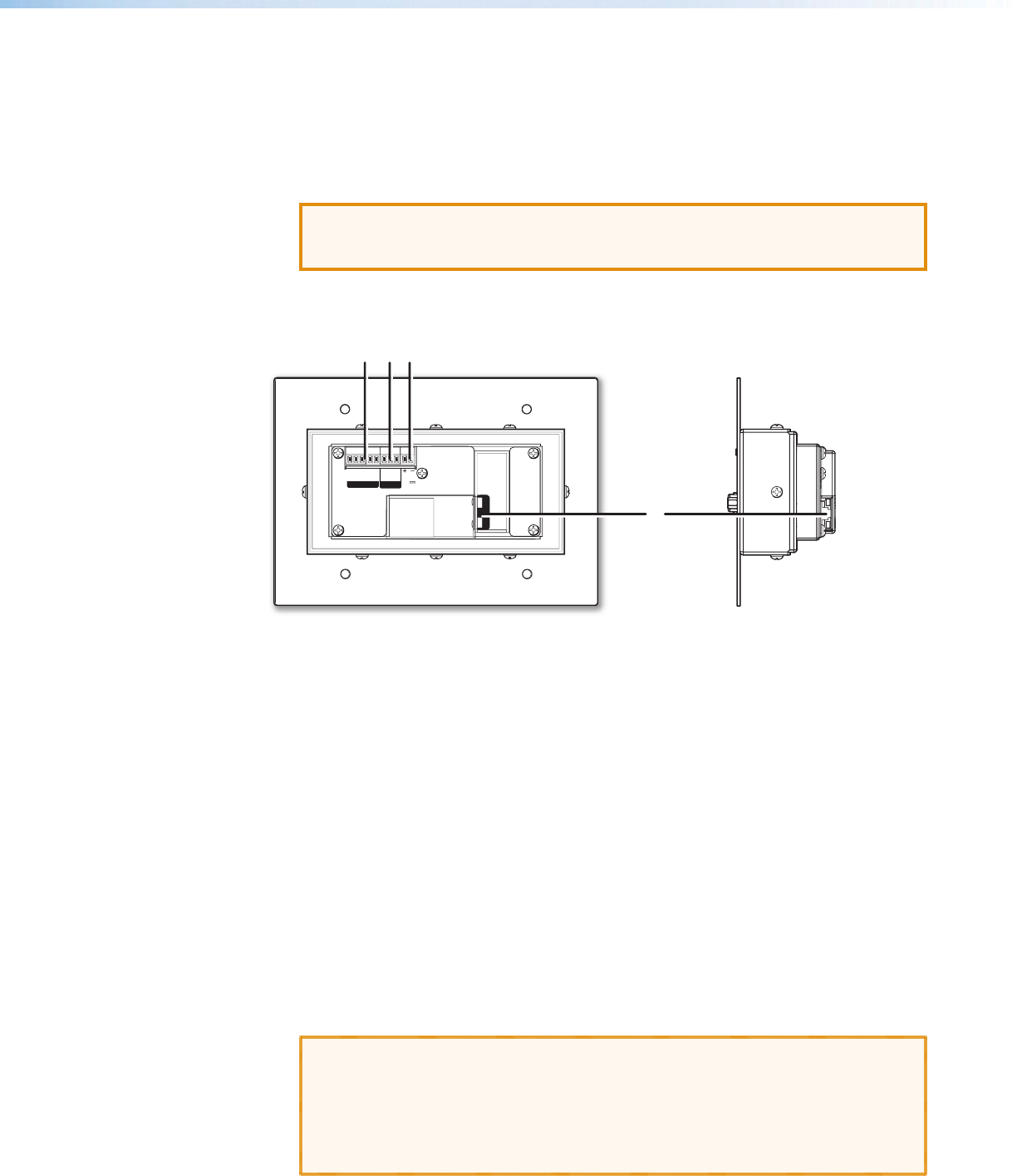
Figure 5. Rear Panel Connectors
a XTP Connector — Connect a twisted pair cable to the RJ-45 connector labeled
XTP Out on the XTP T UWP 302 and the XTP input port on another XTP device to pass
all signals (see TP Cable Termination and Recommendations on page 11). This
cable carries the following signals:
• Digital video
• Digital audio
• Bidirectional RS-232 and IR commands
• Remote power
• Ethernet communication
• System communication
Signal LED indicator — Lights green when the transmitter outputs an XTP signal or
test pattern to a compatible receiver or matrix switcher.
Link LED indicator — Lights yellow when XTP devices are connected and
communication is established.
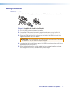
ATTENTION:
• Do not connect this connector to a computer data or telecommunications
network.
• XTP remote power is intended for indoor use only. No part of the network that
uses XTP remote power should be routed outdoors (see Remote power on
page 14).